
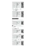
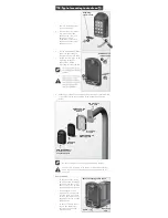


17. Fitting the anti-tamper switch
If the onboard terminals are used to connect the anti-
tamper switch, the switch’s normally-closed (N/C) and
common connections MUST be used. Normally-closed (N/C)
will be connected to In1 and COM to Neg (-)
If the anti-tamper switch is to be connected to a third-party
alarm system, either normally-closed or normally-open can
be used, along with a common connection
To third party
alarm system
Onboard alarm option -
activates Alarm Channel
(Channel 3)
OR
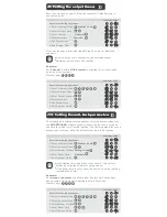
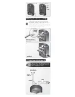
18. Typical connection diagram
If your supply voltage to the SMARTGUARD exceeds
24V AC or 30V DC, fit the supplied 150R resistor in
series with the supply wire as shown.
From external
12V - 24V DC/AC
power supply
Cable
Gooseneck cable route
Knockout
tab
Cable
1
2
3
4
5
6
7
8
9
To other
equipment
Free
exit
Resistor
Door
strike
12V AC
220V
AC
External wiring cable route


