background image

page 8

www.centsys.com

S

ECTION

 5

INS

TALLATION

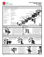
Lift the motor with the inserted 

brackets and place over the 

mounting bolts and fasten them 

using the provided M10 washer and 

M10 nut

FIGURE 12

With the brackets mounted in 

position, insert and and align the 

bracket strap in position as shown in 

Figure 13.

Insert the front bar and discus 

padlock assembly through the 

mounting brackets and bracket strap 

assembly. Lock the front bar into 

position

FIGURE 13

FIGURE 14

Always unlock the discus 

padlock before placing the 

front bar into position

Summary of Contents for D5-EVO

Page 1: ...D5 EVO THEFT RESISTANT CAGE KIT INSTALLATION MANUAL THEFT RESISTANT CAGE Centurion Systems Pty Ltd www centsys com...

Page 2: ...without obligation to notify any persons of any such revisions or changes Additionally Centurion Systems Pty Ltd makes no representations or warranties with respect to this manual No part of this docu...

Page 3: ...em can be operated safely IMPORTANT SAFETY INSTRUCTIONS Warnings for the installer CAREFULLY READ AND FOLLOW ALL INSTRUCTIONS before beginning to install the product Do not in any way modify the compo...

Page 4: ...gainst theft Disclaimer Due to continuous improvement in the design and manufacture of this product the actual product may differ slightly in appearance to that which is depicted herein Centurion Syst...

Page 5: ...tion 3 Required Tools FIGURE 2 PRODUCT IDENTIFICATION 1 5 6 1 Theft resistant cage overstrap 2 Closed up mounting bracket 3 Mounting bracket 4 Discus padlock 5 Front bar 6 Padlock enclosure 1 Spanner...

Page 6: ...ng so FIGURE 3 FIGURE 5 FIGURE 7 FIGURE 8 FIGURE 4 FIGURE6 Unlock the discus padlock Locate the padlock enclosure on the front bar With the key in the lock insert the discus padlock through the openin...

Page 7: ...PORTANT For magnetic origin operator models relocate gate magnet as close as possible to operator cover and reset gate Limits Remove the side covers to access the mounting bolts Remove the mounting nu...

Page 8: ...and M10 nut FIGURE 12 With the brackets mounted in position insert and and align the bracket strap in position as shown in Figure 13 Insert the front bar and discus padlock assembly through the mounti...

Page 9: ...page 9 www centsys com A finished installation should look like Figure 15 FIGURE 15 SECTION 5 INSTALLATION...

Page 10: ...ON OF TRAVEL 8 Installation handover Notes Once the Theft resistant cage has been successfully installed and its operation tested it is important for the operation and safety considerations to be expl...

Page 11: ...page 11 www centsys com SECTION 5 RHS SURFACE MOUNT SIMILAR DIRECTION OF TRAVEL Notes NOTES...

Page 12: ...30 GMT 2 E OE Centurion Systems Pty Ltd reserves the right to change any product without prior notice All product and brand names in this document that are accompanied by the symbol are registered tra...

Reviews: