Central Pneumatic 66801 Set Up And Operating Instructions Manual Download Page 11

ImPOrtant:  clean the spray gun ImmedIately after use.

Improper cleaning will cause the spray gun not to work.

SKU 66801       


Page 11

For technical questions, please call 1-800-444-3353;

troubleshooting section near the end of manual.
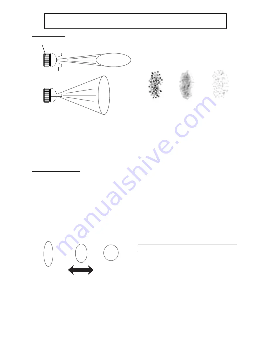
Fan direction

Figure 4

Horizontal Fan

Vertical 

Fan

Air Cap (1)

Lock Ring

1.  To change the direction of the fan 

from horizontal to vertical, loosen the 

Lock Ring and turn the Air Cap (1) 90 

degrees. After the adjustment, tighten 

the Lock Ring by hand - See Figure 

4.

Pattern adjustment

warnIng! never exceed the maxi-

mum operating pressure.

Adjust the air pressure during op

-

1. 

eration with the Trigger (36) fully 

depressed and the Air Control Knob 

(19) fully open. If you need to reduce 

the air pressure for specific areas, 

use the Air Control Knob or adjust the 

air compressor.

Figure 5 

Flat/Open

Round/Closed

2. 

To set the spray pattern size specific 

to the job, use the Pattern Control 

Knob (23). Turn the Pattern Control 

Knob counterclockwise (all the way 

open) to flatten the spray pattern. 

Turn it clockwise for a round spray 

pattern - See Figure 5.
Turn the Fluid Control Knob (12) 

3. 

clockwise until it is fully closed.

Figure 6 

Too Fine

(Loosen)

Too Coarse

  (Tighten)

Correct

4.  After setting up a piece of scrap 

material, squeeze the Trigger (36) 

in short bursts while tuning the Fluid 

Control Knob (12) counterclockwise 

and observe the spray patterns until 

you see the pattern you want. Also, 

look at the pattern for consistency. 

Too much air may cause the spray 

to come out too fine. Reduce the air 

pressure or allow more material to 

come out by opening the Fluid Con-

trol Knob (12). If the spray appears 

too thick (you see globs of paint), 

close down the Fluid Control Knob 

slowly, checking the mixture after 

each adjustment. Use the counter nut  

next to the Fluid Control Knob to lock 

the setting in place.

work Piece and work area set up

Designate a work area that is clean 

1. 

and well-lit. The work area must not 

allow access by children or pets to 

prevent injury and distraction.

Route the air hose along a safe route 

2. 

to reach the work area without creat-

ing a tripping hazard or exposing the 

air hose to possible damage. The air 

hose must be long enough to reach 

Summary of Contents for 66801

Page 1: ...ave this manual Copyright 2009 by Harbor Freight Tools All rights reserved No portion of this manual or any artwork contained herein may be reproduced in any shape or form without the express written...

Page 2: ...safety 4 Tool use and care 4 Service 5 Air source 5 Symbols and Specific Safety Instructions 6 Symbol Definitions 6 Functional Description 8 Specifications 8 Components and Controls 8 Initial Tool Se...

Page 3: ...ituation which if not avoided could result in death or serious injury CAUTION used with the safety alert symbol indicates a hazardous situation which if not avoided could result in minor or moderate i...

Page 4: ...e f Always wear eye protec tion Wear ANSI ap proved safety goggles and full face shield Tool use and care Use clamps or another practical a way to secure and support the workpiece to a stable platform...

Page 5: ...a only by qualified repair personnel When servicing a tool use only b identical replacement parts Use only authorized parts Use only the lubricants supplied c with the tool or specified by the manufac...

Page 6: ...ularly when sprayed Maintain a distance of at least 25 feet from the air compressor If possible locate the air compressor in a separate room Read all of the information concern 3 ing coating products...

Page 7: ...nia Health Safety Code 25249 5 et seq WARNING The brass components of this product contain lead a chemi cal known to the State of California to cause birth defects or other repro ductive harm Californ...

Page 8: ...moisture trap element spare batteries Components and Controls Air Cap 1 Cup Assembly 6 Pattern Control Knob 23 Air Control Knob 19 Air Inlet 35 Trigger 36 Fluid Control Knob 12 Figure 1 Digital Displ...

Page 9: ...ven if the air hose is ruptured The shutoff valve should be a ball valve be cause it can be closed quickly Note Do not use an oiler system with this tool The oil will mix with the material being prope...

Page 10: ...wered Operating Instructions Read the entire Important Safety Information section at the beginning of this manu al including all text under sub headings therein before set up or use of this product In...

Page 11: ...n the spray pattern Turn it clockwise for a round spray pattern See Figure 5 Turn the Fluid Control Knob 12 3 clockwise until it is fully closed Figure 6 Too Fine Loosen Too Coarse Tighten Correct 4 A...

Page 12: ...VLP the dynamic air pressure going in the Air Cap 1 must be a maximum of 10 PSI The lower the air pressure the less bounce back and overspray Due to the viscosity of latex and other water based paints...

Page 13: ...tance from the object being painted at 6 to 9 This may slightly differ de pending on the flow adjustment and the material being sprayed Figure 9 Top View End Stroke Begin Stroke Release Trigger Squee...

Page 14: ...Lubrication Note These procedures are in addition to the regular checks and maintenance explained as part of the regular op eration of the air operated tool Use the Accessory tools shown in the Compo...

Page 15: ...g 10 Air Cap 1 Needle 9 Figure 10 5 Disassemble the tool using the tools provided Use the 9 Way Flat Wrench to remove the Air Cap 1 Unscrew the Fluid Control Knob 12 and care fully remove the Needle S...

Page 16: ...olu tions according to the solution manu facturer s directions and local hazard ous waste standards Daily Air Supply Maintenance Every day perform maintenance on the air supply according to the com po...

Page 17: ...losed The material is too thick 2 The air pressure is too low 3 Open Pattern Control Knob 23 1 Thin material according to the 2 manufacturer s instructions Increase air pressure within the Maximum 3 P...

Page 18: ...uid too thick 3 Check air hoses 1 Open fluid control 2 Thin fluid or increase air pressure within 3 Maximum range Overspray Improper application speed 1 Improper distance from 2 workpiece Too much air...

Page 19: ...T Part Description Qty 19 Air Control Knob 1 20 Pattern Adjustment Valve 1 21 Pattern Adjustment Seat 1 22 Pattern Sealed Gasket 1 23 Pattern Control Knob 1 24 Cross Bolt 1 25 Valve Sealed Screw 1 26...

Page 20: ...and an explanation of the com plaint must accompany the merchandise If our inspection verifies the defect we will ei ther repair or replace the product at our election or we may elect to refund the pu...

Reviews: