background image

Page 8

SKU 47612

For technical questions, please call 1-800-444-3353.

Operating the Nailer

ALWAYS  WEAR ANSI AppROVEd  ImpAct  SAFEtY  GOGGLES  WHEN 

RELOAdING  OR  dOING ANY  OtHER  mAINtENANcE  ON  tHIS  tOOL. 

Other people in the work area must also wear ANSI approved impact safety 

goggles.

Attach the Nailer to the air supply at the Air Inlet (57).  Start your compressor and 

1. 

check the pressure making sure it is set at the recommended 70-120 PSI.

Rotate the Deflector (6) so that the exhaust air blast will be directed away from the 

2. 

operator.

To fire, place the Nose Cushion (89) of the Nailer on the workpiece.  With the 

3. 

Trigger (47), Nails can only be driven one way.  First, depress the Nose Cushion 

against the workpiece.  Then, pull the Trigger.  The Nailer should not fire if the 

Nose Cushion is not depressed.  This feature is helpful when precise fastener 

placement is required.  Also, it may reduce the possibility of injury to you or to oth-

ers working with you.
Do not press the Nose Cushion (89) against the work surface with extra force.  Al-

4. 

low the tool to do the work.  Always allow the tool to recoil off the work surface.

When finished using the Nailer, always disconnect the tool from its compressed 

5. 

air supply.  Empty the Magazine (69) completely of nails.  Attempt to fire the Nailer 

into a piece of scrap wood to ensure it is disconnected and is incapable of firing 

any nails.
Make sure to store the Nailer in its accessory Carrying Case and in a clean, dry, 

6. 

safe location out of reach of children.

REV 06k

Summary of Contents for 47612 Contractor Series

Page 1: ...ual Copyright 2005 by Harbor Freight Tools All rights reserved No portion of this manual or any artwork contained herein may be reproduced in any shape or form without the express written consent of Harbor Freight Tools Diagrams within this manual may not be drawn proportionally Due to continuing improvements actual product may differ slightly from the product described herein Tools required for a...

Page 2: ...d this manual for the safety warnings and precautions assembly operat ing inspection maintenance and cleaning procedures parts list and assembly diagram Keep your invoice with this manual Write the invoice number on the inside of the front cover Keep this manual and invoice in a safe and dry place for future reference Safety Warnings and Precautions WARNING When using tool basic safety precautions...

Page 3: ...ubricating and changing accessories Inspect tool cords and air hoses periodically and if damaged have them repaired by an authorized technician The handle must be kept clean dry and free from oil and grease at all times Do not operate a tool if any portion of the tool s operating controls are inop erable disconnected altered or not working properly Disconnect Air Hose and release any built up air ...

Page 4: ...k your air compressor s manual for the appropriate size cord It is also possible that the use of an extension cord may cause your circuit breaker to trip or your panel fuse to break If this happens either use the compressor without an extension cord or find a larger amperage circuit to use Maintenance 19 The maintenance outlined in the maintenance section should be performed regularly For your saf...

Page 5: ...r masonry products Arsenic and chromium from chemically treated lumber California Health Safety Code 25249 5 et seq Stay within air pressure capacity 27 Never operate the Nailer above 120 PSI Hold tool away from head and body 28 During operation the Nailer may kick back causing injury Transport Nailer safely 29 Always disconnect air supply when moving the tool in the workplace Carry the tool by th...

Page 6: ...ng Even though the nailer should be empty during this procedure ALWAYS point the nailer at a piece of scrap wood when testing Make sure the tool is disconnected from the air supply 1 Completely empty the Magazine 69 of nails 2 The Nailer should not fire if the nose is not depressed against the workpiece 3 Make sure the Trigger 47 and nose move freely without sticking see the illustra 4 tion on the...

Page 7: ...fied service technician Loading Nails ALWAYS WEAR ANSI APPROVED IMPACT SAFETY GOGGLES WHEN RELOADING OR DOING ANY OTHER MAINTENANCE ON THIS TOOL Other people in the work area must also wear ANSI approved impact safety goggles Warning Make sure the Nailer is not attached to the air hose whenever loading the tool 1 Insert the Nails into the opening in the End Plate 81 and into the Magazine 69 lettin...

Page 8: ...one way First depress the Nose Cushion against the workpiece Then pull the Trigger The Nailer should not fire if the Nose Cushion is not depressed This feature is helpful when precise fastener placement is required Also it may reduce the possibility of injury to you or to oth ers working with you Do not press the Nose Cushion 89 against the work surface with extra force Al 4 low the tool to do the...

Page 9: ...olled manner If the pusher cannot eject all the nails including the jammed nail s then have the assistant hold the pusher back while you use a pair of needle nose pliers not included to remove the jammed nail s usually from the Driver Guide 59 area Then slowly bring the Pusher forward to empty the magazine ensuring no jams remain 4 Replace the Driver Guide Cover A close the Lock Handle Unit and re...

Page 10: ...e only to be attempted by a qualified technician Please Read the Following Carefully THE MANUFACTURER AND OR DISTRIBUTOR HAS PROVIDED THE PARTS LIST AND ASSEMBLY DIAGRAM IN THIS MANUAL AS A REFERENCE TOOL ONLY NEITHER THE MANUFACTURER OR DISTRIBUTOR MAKES ANY REPRESENTATION OR WARRANTY OF ANY KIND TO THE BUYER THAT HE OR SHE IS QUALIFIED TO MAKE ANY REPAIRS TO THE PRODUCT OR THAT HE OR SHE IS QUAL...

Page 11: ... Grommet 35 Valve 36 O Ring 37 O Ring 38 O Ring 39 Valve Plunger 40 O Ring 41 Spring 42 Trigger Valve Stem 43 O Ring 44 Cap Plunger 45 O Ring 46 Secondary Trigger 47 Trigger 48 Rolled Pin 49 Rolled Pin 50 Roll Pin Early Units 51 Retainer 52 Gun Body 53 Gasket End Cap 54 End Cap 55 Lock Washer 56 Bolt 57 Air Inlet 58 Protective Cover 59 Driver Guide 60 Driver Guide B 61 Lock Nut 62 Safety Guide 63 ...

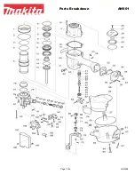
Page 12: ... 12 SKU 47612 For technical questions please call 1 800 444 3353 ASSEMBLY DIAGRAM NOTE Some parts are listed and shown for illustration purposes only and are not available individually as replacement parts ...

Reviews: