SKU 97524
40116
Page 9
For technical questions, please call 1-800-444-3353.
Maintenance
Warning!
Always disconnect the tool from the air compressor and then empty the magazine
of nails or staples before attempting to inspect or perform maintenance to the Nailer/
Stapler.
1. Inspect all of the nuts and screws and make sure they are securely fastened.
2. Periodically lubricate the driving mechanism and magazine with a light oil. Wipe down
with a clean cloth. Never use gasoline or flammable solvents to clean the tool.
3. Inspect your air compressor according to manufacturer’s instructions.
Warning!
If you detect any air leaks, power loss, the Nailer/Stapler skips driving, drives too
deep, or not deep enough, take the Nailer/Stapler to a qualified service technician.
PLEASE READ THE FOLLOWING CAREFULLY
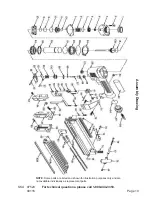
THE MANUFACTURER AND/OR DISTRIBUTOR HAS PROVIDED THE PARTS DIAGRAM IN THIS MANUAL
AS A REFERENCE TOOL ONLY. NEITHER THE MANUFACTURER NOR DISTRIBUTOR MAKES ANY
REPRESENTATION OR WARRANTY OF ANY KIND TO THE BUYER THAT HE OR SHE IS QUALIFIED TO
MAKE ANY REPAIRS TO THE PRODUCT OR THAT HE OR SHE IS QUALIFIED TO REPLACE ANY PARTS
OF THE PRODUCT. IN FACT, THE MANUFACTURER AND/OR DISTRIBUTOR EXPRESSLY STATES THAT
ALL REPAIRS AND PARTS REPLACEMENTS SHOULD BE UNDERTAKEN BY CERTIFIED AND LICENSED
TECHNICIANS AND NOT BY THE BUYER. THE BUYER ASSUMES ALL RISK AND LIABILITY ARISING
OUT OF HIS OR HER REPAIRS TO THE ORIGINAL PRODUCT OR REPLACEMENT PARTS THERETO, OR
ARISING OUT OF HIS OR HER INSTALLATION OF REPLACEMENT PARTS THERETO.
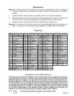
Parts List
Part Description
1
Exhaust Deflector
3
Hex. Bolt
4
Head Cap
5
Seal
6
Internal Lining
7
O-Ring
8
Compression Spring
9
Gasket
10 O-Ring
11 Head Valve Piston
12 O-Ring
13 O-Ring
14 O-Ring
16 O-Ring
17A Piston & Driver
26 Body
27 Nozzle
35
Compression Spring
37 Spring Pin
38 E-Ring
Part Description
39 Trigger
40 Retainer Pin
41 Safety Guide
42 Spring Washer
43 Hex Bolt
44 Spring Pin
45 Spring
46 Screw Nut
47 Thumb Wheel
48 Spring
49 Steel Ball
50 Stopper
51 E-Ring
52 Safety
53 Safety Cover Bolt
54 Safety Cover
55 Hex. Bolt
56 Spacer
57 Driver Cover
58 Driver Guide
59 Hex. Bolt
60 Pin
Part Description
61A Magazine B
62A Steel Bar
63 Pusher Unit
64 Spring Holder
66 Spring
67A Magazine A
68 Stopper
69 Hex. Bolt
70 Hex. Bolt
71A Nail Positioner
72 Retaining Pin
73 Latch
74 Spring
75 O-Ring
76 Hex Bolt
77 Cylinder Pin
78 Tail Cover
79 Hex. Bolt
80 Hex. Bolt
81 Tail Hanger
82 Lock Nut
83 Hand Grip
Part Description
84 O-Ring
85 End Cap
86 Air Plug
87 Collar
88 Fixed Ring
89 O-Ring
90 Lining Ring
91 O-Ring
92 Cylinder
93 Lining Ring
94 Bumper
95 Seal
96
Trigger Valve Upper
97 Trigger Plunger
98 O-Ring
99 O-Ring
100
Trigger Valve Lower
101 Trigger Plate
102 Non-mar Tip


