Page 11
SKU 95906
For technical questions, please call 1-800-444-3353.
Before each use, inspect the general condition of the Mortar Mixer. Check for loose
bolts and nuts, misalignment, binding of moving parts, loose or broken parts, Engine
problems, and any other condition that may affect the safe operation of the Mortar
Mixer. If abnormal noise or vibration occurs, turn off the Mortar Mixer immediately
and have the problem corrected before further use.
do not use damaged equipment.
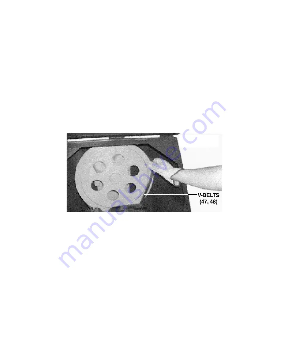
To change the V-Belts (47, 48), loosen the four Hex Bolts located at the base of
the Engine. Slide the Engine to the left to loosen the V-Belts. Then, remove the V-
Belts as shown in the following illustration. Replace the old V-Belts with new V-Belts
(types A890 and A950). Then slide the Engine to the right to tighten the V-Belts to
the proper tension. Correct tension is obtained when there is approximately 1/4”
deflection of the V-Belts at the center span of the Pulleys (40, 41 and 49, 50). Do
not over-tension. Then, retighten the four Hex Bolts located at the base of the En-
gine.
(see Figure F.)
2.
3.
Thoroughly clean the Cement Mixer at the end of each day’s operation. The Drum
(55) may be scoured for approximately two minutes, using a gravel and water mixture.
Then discharge the gravel/water mixture and hose down the Drum inside and out.
Dried cement mix should be scraped out of the Drum (55). Do not beat on the
Drum with a shovel or other tools to break up accumulations of dried cement mix,
as damage to the Cement Mixer may result.
Do not pour water over the Engine (34). Refer to the Engine manufacturer’s instruc-
tion manual for all inspection, maintenance, and cleaning procedures.
Periodically, lubricate all moving parts of the Cement Mixer.
IMPORTAnT:
Whenever a Hub (7) is disassembled for maintenance the following
procedure MUST be followed:
nOTE:
A bearing packer (not included) must be
used for this procedure.
Using a suitable solvent, thoroughly clean the Bearing (7), Oil Seal (10), Castle
Nut (12), Cotter Pin (13), and the rest of the parts of the Hub assembly of all old
4.
5.
6.
7.
8.
a.
FIGURE F
07h


