background image

Page 11

For technical questions, please call 1-800-444-3353.

SKU 67414 


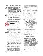
Carefully fill (approximately 8-1/2 

3. 

ounces) the Gearbox (8a).  
Wipe up any spilled oil.

4. 

Replace the Oil Fill Plug and tighten 

5. 

securely.

note:  

Do not use dirty, used, or 

otherwise contaminated gear oil.  

Damage may occur to the internal 

mechanisms of the Gearbox (8a).

caution!

  Do not run the engine with too 

little or too much oil.  The engine will 

be permanently damaged.

operatinG instructions

  before starting the engine:

Follow the set up 

a. 

instructions to prepare the 

equipment.

inspect the equipment and 

b. 

engine.

Fill the engine with the 

c. 

proper amount and type of 

fuel mixture and gearbox oil.

read the section that follows.

d. 

Place the Auger Drill on its side with 

1. 

its Auger (33a) resting upon the 

ground surface location that is to be 

drilled.  

Make sure that no debris, clothing, 

2. 

or other objects are near the auger 

bit.  Keep all bystanders away.

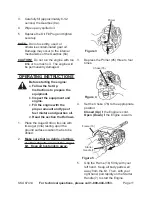
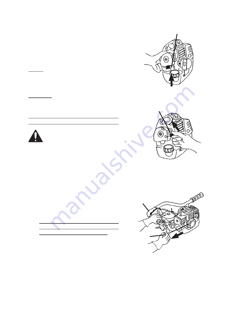
Primer

Figure 3

3.  Depress the Primer (95) three to four 

times. 

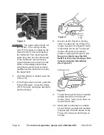
Choke (76)

Figure 4

4.  Set the Choke (76) to the appropriate 

position: 

closed (up) 

if the Engine is cold.


open (down) 

if the Engine is warm.

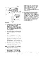
Frame (1b)

Starter 

Handle (7)

Figure 5

5. 

Grip the Frame (1b) firmly with your 

left hand.  Keep all body parts well 

away from the bit.  Then, with your 

right hand, pull rapidly on the Starter 

Handle (7) to start the Engine.  

Summary of Contents for 67414

Page 1: ...ttp www harborfreight com Read this material before using this product Failure to do so can result in serious injury Save this manual Copyright 2009 by Harbor Freight Tools All rights reserved No portion of this manual or any artwork contained herein may be reproduced in any shape or form without the express written consent of Harbor Freight Tools Diagrams within this manual may not be drawn propo...

Page 2: ...rocedures 14 Daily Maintenance 14 Air Filter Element Maintenance 15 Spark Plug Maintenance 15 Fuel Filter Maintenance 15 Cleaning Maintenance and Lubrication Schedule 16 Every Month in dirty environments 16 Every 3 Months or 50 Operation Hours 16 Every 6 Months or 100 Operation Hours 16 Every 300 Operation Hours 16 Every 3 years 16 Storage 16 Troubleshooting 17 Engine Parts List 20 Engine assembly...

Page 3: ... the safety alert symbol indicates a hazardous situation which if not avoided could result in minor or moderate injury NOTICE is used to address practices not related to personal injury CAUTION without the safety alert symbol is used to address practices not related to personal injury WARNING Read all instructions Failure to follow all instructions listed below may result in fire serious injury an...

Page 4: ...evel solid surface and brace against torque during use Keep hands and feet away from auger bit and hole when engine is running Disconnect and insulate spark plug 5 wire before maintenance and or changing bits Never disable safety switches or 6 components Do not carry between holes with 7 engine running Carry by handle only not by bit 8 Gasoline fumes are explosive Never 9 smoke or refill with engi...

Page 5: ... interference or pacemaker failure Caution is necessary when near the engine s magneto or recoil starter Engine should be off during distributor adjustment Use only accessories that are 24 recommended by Harbor Freight Tools for your model Accessories that may be suitable for one piece of equipment may become hazardous when used on another piece of equipment Do not operate in explosive 25 atmosphe...

Page 6: ...equipment for a purpose for which it is not intended Vibration Hazard This tool vibrates during use Repeated or long term exposure to vibration may cause temporary or permanent physical injury particularly to the hands arms and shoulders To reduce the risk of vibration related injury Anyone using vibrating tools regularly 1 or for an extended period should first be examined by a doctor and then ha...

Page 7: ...e Maintain labels and nameplates 5 on the equipment These carry important information If unreadable or missing contact Harbor Freight Tools for a replacement Have the equipment serviced by a 6 qualified repair person using only identical replacement parts This will ensure that the safety of the equipment is maintained Do not attempt any service or maintenance procedures not explained in this manua...

Page 8: ...andards set by the U S Environmental Protection Agency For warranty information refer to the last pages of this manual At high altitudes the engine s carburetor governor if so equipped and any other parts that control the fuel air ratio will need to be adjusted by a qualified mechanic to allow efficient high altitude use and to prevent damage to the engine and any other devices used with this prod...

Page 9: ...ious injury Operate only with proper spark arrestor installed Operation of this equipment may create sparks that can start fires around dry vegetation A spark arrestor may be required The operator should contact local fire agencies for laws or regulations relating to fire prevention requirements Note For additional information regarding the parts listed in the following pages refer to the Assembly...

Page 10: ...ge the unit Check the fuel level before every use If needed add the proper fuel mixture as follows To obtain the proper 25 1 fuel mix 1 combine 25 parts unleaded gasoline 89 octane with 1 part 2 cycle oil in the provided Fuel Mix Container 36a Cover and gently agitate to thoroughly mix before each fueling Refer to the chart below for proper mix quantities FUEL MIX QUANTITIES Ratio 2 Stroke Engine ...

Page 11: ...quipment and b engine Fill the engine with the c proper amount and type of fuel mixture and gearbox oil Read the section that follows d Place the Auger Drill on its side with 1 its Auger 33a resting upon the ground surface location that is to be drilled Make sure that no debris clothing 2 or other objects are near the auger bit Keep all bystanders away Primer Figure 3 3 Depress the Primer 95 three...

Page 12: ...ne 7 does not start press the Primer 95 again Close the Choke 76 if it is open and again attempt to start the Engine Figure 7 Speed Control 10b 8 As soon as the Engine is running check to make sure the Choke 76 is open Squeeze the Speed Control 10b briefly and let up The Speed Control will revert to its original position causing the Engine to idle Keep your thumb near the Kill Switch in the event ...

Page 13: ...ong twisting forces produced by the drill during operation Release the Speed Control 10b 14 as soon as the drilling is completed allowing the Engine to idle Note Avoid running the Auger Drill at full throttle without a drilling load After running the Auger Drill for an 15 extended period of time allow the Engine to idle for several minutes to dissipate the heat This will prevent some Engine parts ...

Page 14: ... Procedures Many maintenance procedures including those not detailed in this manual will need to be performed by a qualified technician for safety If you have any doubts about your ability to safely service the equipment or engine have a qualified technician service the equipment instead Note Warranty is void if proper maintenance and servicing procedures are not followed Daily Maintenance Before ...

Page 15: ...olish it using emery paper If the white insulator is cracked or chipped the spark plug needs to be replaced When installing a new spark 4 plug adjust the plug s gap to the specification on the Technical specification chart Do not pry against the electrode or the insulator the spark plug can be damaged Install the new spark plug or the 5 cleaned spark plug into the engine Gasket style Finger tighte...

Page 16: ...Operation Hours Clean replace air filter element a Clean Fuel Filter 84 and Fuel Cap b w Filter Set 94 Replace gear oil in Gearbox c Every 6 Months or 100 Operation Hours Clean replace air filter element a Clean replace spark plug b Every 300 Operation Hours Clean fuel tank and carburetor a Clean carbon build up from b combustion chamber Every 3 years Replace Fuel Filter 84 and Fuel Cap w Filter S...

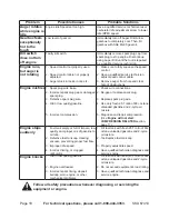
Page 17: ...oke Remove spark plug 7 and pull the start handle several times to air out the chamber Reinstall spark plug and close the choke Clean replace Filter 84 or 94 8 components Ignition spark Related Spark plug wire not connected 1 securely Spark plug electrode wet or dirty 2 Incorrect spark plug gap 3 Spark plug wire or spark plug broken 4 Incorrect spark timing or faulty 5 ignition system Ignition spa...

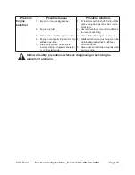
Page 18: ...ap or damaged 2 spark plug Defective spark plug wire 3 Old or low quality gasoline 4 Incorrect compression 5 Check wire connections 1 Re gap or replace spark plug 2 Replace spark plug wire 3 Use only fresh 25 1 ratio of 89 octane 4 unleaded gasoline and 2 cycle oil mixture Diagnose and repair compression 5 Use Engine will not start Compression Related section page 17 Engine stops suddenly Fuel tan...

Page 19: ...ke stuck 5 incorrect timing clogged carburetor or overheated engine Fill fuel tank with fresh 25 1 ratio of 89 1 octane unleaded gasoline and 2 cycle oil mixture Use cold weather fuel and oil additives 2 to prevent backfiring Open choke after engine warms up 3 Qualified technician must adjust engine 4 at altitudes greater than 5 000 feet above sea level Have qualified technician diagnose and 5 ser...

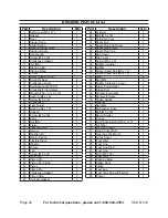
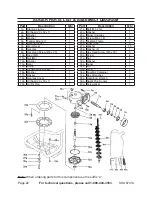
Page 20: ...n 1 42 Piston Pin Circlip 2 43 Piston 1 44 Piston Pin 1 45 Crankcase Gasket 1 46 Piston Ring 2 47 Cylinder Gasket 1 Part Description Qty 48 Cylinder 1 49 Bolt M5 x 18 4 50 Cylinder Cover 1 51 Spark Plug 1 52 Spark Plug Clip Reed 1 53 Spark Plug Cover 1 54 Spark Plug Cap 1 55 Cap Cover 1 56 Top Cover 1 57 Screw M5 x 20 1 58 Muffler Insulator 1 59 Muffler 1 60 Socket Head Bolt M5 x 12 1 61 Socket He...

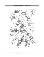
Page 21: ... 67 47 77 57 87 2 7 12 18 28 38 68 48 78 58 88 3 8 13 23 33 63 43 73 53 83 93 19 29 39 69 49 79 59 89 4 9 9 14 24 34 64 44 74 54 84 94 20 30 40 70 50 60 90 5 10 15 25 35 65 45 75 55 85 95 21 31 61 41 71 51 81 91 16 16 26 36 66 46 76 56 86 22 32 42 42 72 52 82 92 Engine assembly diagram ...

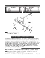
Page 22: ...ng 1 15a Transmission Socket 1 16a Washer 1 17a Gasket 1 18a Gearbox Cover 1 19a Oil Seal 20 x 35 x 7 1 20a Oil Fill Plug 1 Part Description Qty 21a Bolt M6 x 12 1 22a Washer 1 23a Paper Underlay 1 24a Screw M6 x 16 6 25a Cushion Frame 1 26a Liner Tube 5 27a Washer 10 28a Washer 6 1 29a Hex Head Screw M6 x 30 5 30a Screw 4 31a Nut 4 32a Washer 4 33a Auger 1 34a Pin 1 35a R Pin 1 36a Fuel Mix Conta...

Page 23: ... for this component use the suffix b PLEASE READ THE FOLLOWING CAREFULLY The manufacturer and or distributor has provided the parts list and assembly diagram in this manual as a reference tool only Neither the manufacturer or distributor makes any representation or warranty of any kind to the buyer that he or she is qualified to make any repairs to the product or that he or she is qualified to rep...

Page 24: ... Department at 1 800 444 3353 Harbor Freight Tools Emission Control Defects Warranty Provisions 1 Length of Coverage HFT warrants to a first retail purchaser and each subsequent purchaser that the engine is free from defects in materials and workmanship that cause the failure of warranted parts for a period of two 2 years after the date of delivery to the first retail purchaser 2 No Charge Repair ...

Page 25: ...i 3 Ignition System Spark plug i Magneto ignition system ii 4 Catalyst System if so equipped Exhaust pipe stud i Muffler ii Catalytic converter if so equipped iii 5 Miscellaneous Items Used in Above Systems Vacuum temperature and time sensitive valves i and switches Hoses belts connectors and assemblies ii ...

Page 26: ...y or for incidental contingent special or consequential damages arising from the use of our product Some states do not allow the exclusion or limitation of incidental or consequential damages so the above limitation of exclusion may not apply to you This warranty is expressly in lieu of all other warranties express or implied including the warranties of merchantability and fitness To take advantag...

Reviews: