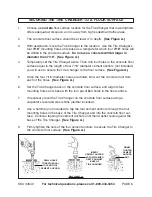
Central Machinery 34542 Assembly And Operating Instructions Manual Download Page 6

4.

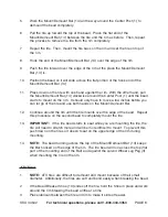
Temporarily set the Tire Changer aside.  Then drill four holes in the concrete floor
surface equal to the 

length of four 7/16” diameter cement anchors (not included)

you will use to secure the Tire Changer to the floor surface.  (See Figure A.)

5.

Once the four 7/16” diameter holes are drilled, blow out the concrete dust from
each of the holes.  (See Figure A.)

6.

Set the Tire Changer back on the concrete floor surface, and align its four
mounting holes at its base with the four pre-drilled holes in the floor surface.

7.

If necessary, level the Tire Changer on the concrete floor surface using a
carpenter’s level and steel shims (neither included).

8.

Use a hammer (not included) to tap the four cement anchors through the four
mounting holes in the base of the Tire Changer and into the concrete floor sur-
face.  Continue tapping the cement anchors until their washer rests against the
base of the Tire Changer.  (See Figure A.)

9.

Firmly tighten the nuts of the four cement anchors to secure the Tire Changer to
the concrete floor surface.  (See Figure A.)

SKU 34542         For technical questions, please call 1-800-444-3353        PAGE 6

DRILL HOLES

TO DEPTH EQUAL

TO LENGTH OF

CEMENT ANCHOR.

INSERT

CEMENT ANCHOR

SO THAT WASHER

RESTS AGAINST

BASE OF

TIRE CHANGER.

FIRMLY

TIGHTEN

CEMENT

ANCHOR

NUT.

FIGURE A

1.

Choose a concrete floor surface location for the Tire Changer that is well lighted,
offers adequate workspace, and is away from high pedestrian traffic areas.

2.

The concrete floor surface should be at least 4” in depth.  (See Figure A.)

3.

With assistance, move the Tire Changer to the location.  Use the Tire Changer’s
four 7/16” mounting holes at its base as a template for which four 7/16” holes will
be drilled in the concrete surface.  Do not use a concrete drill bit larger in
diameter than 7/16”.  (See Figure A.)

SECURING THE TIRE CHANGER TO A FLOOR SURFACE

Summary of Contents for 34542

Page 1: ...D INSTRUCTIONS BEFORE USE Do to continuing improvements actual product may differ slighlty from the product described herein Copyright 2006 by Harbor Freight Tools All rights reserved No portion of th...

Page 2: ...invite accidents 2 Do not operate tools and equipment in explosive atmospheres such as in the presence of flammable liquids gases or dust Tools and equipment can create sparks which may ignite the dus...

Page 3: ...installing this product TOOL USE AND CARE 1 Do not force the tool Use the correct tool for your application The correct tool will do the job better and safer at the rate for which it is designed 2 St...

Page 4: ...ustrial applications must follow OSHA guidelines 4 Never stand on the Tire Changer Serious injury could result if the Tire Changer is tipped 5 Do not allow children and other unauthorized people to ha...

Page 5: ...Never overinflate tires or other inflatable items When inflating a tire with compressed air make sure to inflate the tire to the exact PSI as recommended by the tire manufacturer Always use a pressur...

Page 6: ...pping the cement anchors until their washer rests against the base of the Tire Changer See Figure A 9 Firmly tighten the nuts of the four cement anchors to secure the Tire Changer to the concrete floo...

Page 7: ...ce turn the tire and try again in several loca tions 7 Turn the tire over and repeat Steps 1 through 6 above Demounting And MountingTires 1 After the bead is broken place the tire up on the machine wi...

Page 8: ...move a few inches before you can let go of the tire and use both hands on the Mount Demount Bar 12 Continue around the rim until the tire mounts over the edge of the bead Repeat this procedure on the...

Page 9: ...Changer If abnormal noise or vibration occurs have the problem corrected before further use Do not use damaged equipment 2 To clean the Tire Changer use a mild detergent or mild solvent Then dry 3 CAU...

Page 10: ...PAGE 10 2 4 14 3 5 1 5 6 6 7 6 6 8 8 10 13 9 11 12 11 12 11 11 12 12 9 Part Description Qty Part Description Qty 1 Center Post 1 8 Hump Pin Rings 2 2 Pedestal Cap 1 9 Side Base Channel 2 3 Wheel Lug...

Page 11: ...limitation of exclusion may not apply to you THIS WARRANTY IS EXPRESSLY IN LIEU OF ALL OTHER WARRANTIES EXPRESS OR IMPLIED INCLUDING THE WARRANTIES OF MERCHANTABILITY AND FITNESS To take advantage of...

Reviews: