background image

13

DEUTSCH

–  Entriegeln des beweglichen Griff s (36) durch den Gurt (01).
–  Den Pumparm, mit der der Kopf verbunden ist, betätigen: der Kolben beginnt sich zu bewegen, 
  der Stempel wird dadurch vorangetrieben und es erfolgt das Stanzen des Bleches.

2.4)  Zurückfahren des Stempels 

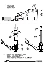
–  Um den Stempel zurückzufahren, drücken Sie kräftig den Druckablaßhebel (44) bis sich der Kolben 
  (16) vollständig zurückgezogen hat.
–  Den Stempel vom Zugbolzen abmontieren und den Stanzabfall aus der Matrize entfernen.
  Überprüfen, dass keine Stanzrückstände innerhalb der Matrize zurückbleiben


(siehe Bild 2).

2.5) Nachbereitung

Das Werkzeug sollte nach Beendigung der Arbeit in die Ausgangsposition gebracht und in die 
Verpackungseinheit gelegt werden. Der Druck muß vorher vollständig abgelassen sein (Druckab-
laßhebel (44) betätigen) und der Pumparm wird mittels Griff halter (01) befestigt.

3.  EINSATZ VON STANZWERKZEUGEN VON FREMDLIEFERANTEN

Um beste Ergebnisse zu erzielen, sollte das Originalstanzzubehör von 

Cembre

 benutzt werden. 

Alternativ dazu kann Stanzzubehör anderer Hersteller mit einem speziellen separat zu bestellenden 
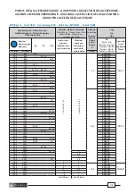
Adapter verwendet werden. Die Kompatibilität der Werkzeuge anhand der Kennwerte des 

HT-FL75


prüfen (siehe Seite 28). 

4.   HINWEISE 

Das Werkzeug ist robust und benötigt keine spezielle Pfl ege oder Instandhaltung. 
Zur Erhaltung der Garantieansprüche beachten Sie folgende Hinweise:

4.1) Pfl ege

Dieses hydraulische Werkzeug sollte vor starker Verschmutzung geschützt werden, da diese für ein 
hydraulisches System gefährlich ist. Jeden Tag nach 
der Arbeit sollte das Werkzeug mit einem Tuch von 
Schmutz und Staub gereinigt werden; besonders 
die beweglichen Teile. 

4.2) Lagerung 

Wenn das Werkzeug nicht benötigt wird, sollte es 
in der Kunststoff kassette gelagert werden, und ist 
somit gegen Beschädigungen wie Stoß und Staub 
geschützt. 
Die Kunststoff kassette Typ 

VAL-P28

 hat folgende 

Abmessungen: 620x360x138 mm (24.4x14.2x5.4 
inches) und ein Gewicht von 2,4 kg (5.3 lbs.), geeig-
net zum Lagern vom Werkzeug und Zubehör sowie 
auch 12 Paar Stanzeinsätzen.

Summary of Contents for HT-FL75

Page 1: ...SATION ET ENTRETIEN BEDIENUNGSANLEITUNG MANUAL DE USO Y MANTENIMIENTO MANUALE D USO E MANUTENZIONE HYDRAULIC PULLER TYPE PUNCHING TOOL OUTIL HYDRAULIQUE EMPORTE PIECE HYDRAULISCHES LOCHSTANZWERKZEUG HERRAMIENTA HIDRAULICA PERFORADORA UTENSILE OLEODINAMICO FORALAMIERE 15 M 111 HT FL75 15 M 111 ...

Page 2: ...truzioni contenute in questo manuale When operating the tool keep hands away from the danger zone Au cours de l utilisation tenir les mains éloignées de la zone de danger Während der Arbeit nicht mit den Händen in den Gefahrenbereich fassen Durante su utilización mantenga las manos fuera de la zona de peligro Durante l utilizzo mantenere le mani fuori dalla zona di pericolo Always wear safety glas...

Page 3: ...ended Accessories from other suppliers may not be designed to withstand the force generated by this tool and may be damaged or break with potential risk of serious injury 1 GENERAL CHARACTERISTICS Application range suitable for punching single layers of stainless steel mild steel fibreglass and plastic material Max puncing capacity ø 140 mm 5 5 in Developed force 75 kN 8 4 sh ton Max operating pres...

Page 4: ...ral bit supplied with the tool and widen it with the KIT RD30 5SS Fully screw the draw stud TD 28 5 supplied with the Punching Kit into the ram 7 of the head Continue as described in points 3 and 4 above Square and rectangular holes Ref to Fig 4 With a drill make the required pilot hole in the plate at the desired point Fully screw the draw stud supplied with the Punching Kit into ram 16 of the he...

Page 5: ...alternative it is possible to use punching accessories made by other manufacturers by requesting separately the specific adaptor Check the compatibility of the accessories with the characteristics of the HT FL75 tool see page 28 4 WARNING The tool is robust completely sealed and requires very little daily maintenance Compliancewiththefollowingpointsshouldhelptomaintaintheoptimumperformanceofthetool...

Page 6: ...irected in paragraph 5 2 h Fit reservoir cap 02 i Assemble main handle 04 to tool body If the tool continues to malfunction return the tool for service repair as detailed in 6 5 2 Oil top up Every six months check the oil level in the reservoir If necessary top up the oil level to the top lip of the reservoir and remove all air from the reservoir see 5 1 points a b c and e finally complete with ope...

Page 7: ...accessoires de perçage d autres fabricants pourraient s abîmer ou ne pas résister à la force générée par cet outil ce qui aurait des conséquences également graves pour la sécurité des personnes 1 CARACTERISTIQUES GENERALES Domaine d application conçu pour percer des tôles d acier inoxydable l acier doux des parois en fibre de verre et la matière plastique Capacité de perforation max ø 140 mm 5 5 in...

Page 8: ... avant trou avec le foret hélicoïdal ø 11 5 mm fourni avec l outil et l élargir avec le KIT RD30 5SS Visser complètement le tirant TD 28 5 fourni avec le kit de perçage dans le piston 7 de la tête Continuer comme décrit aux points précédents 3 et 4 Trous carrés et rectangulaires Réf a Fig 4 A l aide d une perceuse faire un avant trou dans la tôle à l endroit établi Visser complètement le tirant fo...

Page 9: ...originauxCembre sinonilestpossibled utiliserdesaccessoiresdeperçaged autresfabricantsqui exigent leurs propres kits d adaptation spécifiques Vérifier la compatibilité des accessoires avec les caractéristiques de l outil HT FL75 Voir page 28 4 PRECAUTIONS Cet outil est robuste complètement scellé et ne nécessite aucune préoccupation ou entretien particulier Les recommandations qui suivent sont néanmo...

Page 10: ...r doit être complétement évacué Si le niveau d huile est bas un complément doit être fait comme mentionné à 5 2 h Refermer le bouchon 02 i Ensuite remonter le bras principal 04 Dans l éventuel cas où malgré cette intervention l outil ne fonctionnerait pas correctement il est recommandé de le retourner à Cembre pour une révision complète voir 6 5 2 Complément d huile La présence de bulles d air est...

Page 11: ...r dem Stempel aufhalten Es wird die Verwendung des Stanzzubehörs von Cembre empfohlen Stanzzubehör anderer Hersteller könnte sich beschädigen oder der von diesem Werkzeug erzeugten Kraft nicht standhalten Daraus leitet sich eine große Gefahr für die Unversehrtheit des Personals ab 1 ALLGEMEINE EIGENSCHAFTEN Anwendungsbereich geeignetzumStanzenvonrostfreiemStahlblech Weichstahl Materialaus Glasfase...

Page 12: ...r ø 29 mm benutzen Alternativ dazu kann die Pilotbohrung mit dem Bohrer der Größe ø 11 5 mm Anschließend die Bohrung mit dem KIT RD30 5SS erweitern Den Zugbolzen TD 28 5 er ist im Lieferumfang des KIT RD enthalten vollständig in den Kolben 7 des Kopfes eindrehen Gemäß den vorher beschriebenen Punkten 3 und 4 fortfahren Quadratische und rechteckige Stanzungen siehe Bild 4 Zur Führung am festgelegte...

Page 13: ...Um beste Ergebnisse zu erzielen sollte das Originalstanzzubehör von Cembre benutzt werden AlternativdazukannStanzzubehörandererHerstellermiteinemspeziellenseparatzubestellenden Adapterverwendetwerden DieKompatibilitätderWerkzeugeanhandderKennwertedesHT FL75 prüfen siehe Seite 28 4 HINWEISE Das Werkzeug ist robust und benötigt keine spezielle Pflege oder Instandhaltung Zur Erhaltung der Garantieansp...

Page 14: ... kann es passieren dasWerkzeug nach diesenWartungsarbeiten nicht oder nicht richtig funktioniert In diesem Fall sollte entspr Pkt 6 verfahren werden 5 2 Öl nachfüllen Luftblasen im Öltank lassen sich vermeiden wenn der Tank stets gut gefüllt ist Deshalb sollte alle 6 Monate der Tank kontrolliert und bei Bedarf aufgefüllt werden Dies erfolgt so wie in den Punkten a b c und e beschrieben wurde Danac...

Page 15: ...Los accesorios de perforación de otros fabricantes podrían dañarse o no resistir a la fuerza generada por este utensilio con consecuencias que pueden ser incluso graves en la integridad personal 1 CARACTERISTICAS GENERALES Campo de aplicación idónea para perforar chapa de acero inoxidable acero dulce paredes de fibra de vidrio y material plástico Capacidad máxima de perforación ø 140 mm 5 5 in Fuer...

Page 16: ... broca de ø 11 5 mm en dotación y ensancharlo con el KIT RD30 5SS EnroscarcompletamenteeltiranteTD 28 5 proporcionadoendotaciónconelkitdeperforación en el pistón 7 de la cabeza Continuar como se describe en los puntos 3 y 4 anteriores Orificios cuadrados y rectangulares Ref en Fig 4 Con un taladro realizar un pre orificio piloto en la chapa en el punto establecido Enroscar completamente el tirante p...

Page 17: ...eden utilizar accesorios de perforación de otros fabri cantes pidiendo por separado los kits de adaptación específicos Comprobar la compatibilidad de los accesorios con las características de la herramienta HT FL75 ver página 28 4 ADVERTENCIAS Esta herramienta es robusta completamente precintada y no requiere cuidados especiales para obtener un funcionamiento correcto bastará con seguir algunas sen...

Page 18: ...talmente Si el nivel de aceite estuviera bajo esté debe completarse como se indica en el Epig 5 2 h Cierre el tapón 02 i Vuelva a ensamblar el brazo principal 04 En el caso inusual de que tras estas operaciones la herramienta no funcionara correctamente le sugerimos que devuelva la herramienta a Cembre para su revisión ver Epig 6 5 2 Rellenado de aceite La presencia de burbujas de aire se evita co...

Page 19: ...i di foratura Cembre Accessori di foratura di altri produttori potrebbero danneggiarsi o non resistere alla forza generata da questo utensile con conse guenze anche gravi sull incolumita personale 1 CARATTERISTICHE GENERALI Campo di applicazione adatto a forare lamiere in acciaio inossidabile acciaio dolce pareti in fibra di vetro e materiale plastico Capacità max di foratura ø 140 mm 5 5 in Forza ...

Page 20: ...o con punta ø 11 5 mm fornita in dotazione e allargarlo con il KIT RD30 5SS Avvitare completamente il tirante TD 28 5 fornito in dotazione al kit di foratura nel pistone 16 della testa Continuare come descritto nei punti 3 e 4 precedenti Fori quadri e rettangolari Rif a Fig 4 Con un trapano eseguire il preforo pilota richiesto nella lamiera nel punto stabilito Avvitare completamente il tirante for...

Page 21: ...e utilizzare accessori di foratura di altri produttori richiedendo separatamente i kit di adattamento specifici Verificare la compatibilità degli accessori con le carat teristiche dell utensile HT FL75 vedi pagina 28 4 AVVERTENZE L utensile è robusto e non richiede attenzioni particolari per ottenere un corretto funzionamento basterà osservare alcune semplici precauzioni 4 1 Accurata pulizia Tenere ...

Page 22: ...olio fosse basso effettuare un rabbocco come indicato al 5 2 h Inserire il tappo 02 i Rimontare il manico fisso 04 Nel caso eccezionale che l utensile anche dopo queste operazioni di manutenzione non funzio nasse correttamente il pistone non avanza o pulsa è consigliabile contattare il più vicino Agente Cembre per la sua completa revisione vedi 6 5 2 Rabbocco dell olio Il serbatoio dell olio deve es...

Page 23: ...23 FIG 3 FIG 2 FIG 1 NO NON NEIN OK Punching scrap Copeau de perçage Stanzabfall Virutas de perforación Sfrido di tranciatura ...

Page 24: ...Zugbolzen Tirante TD 11 Locking ring Virole Kontermutter Contera Ghiera Die Matrice Matrize Matriz Matrice Punch Poinçon Stempel Punzón Punzone Draw Stud Tirant Zugbolzen Tirante Die Matrice Matrize Matriz Matrice Pilot hole Avant trou Pilotbohrung Agujero piloto Preforo pilota 1 16 ...

Page 25: ...ESAMTANSICHT VISTA DEL CONJUNTO VISTA D ASSIEME FIG 6 TOOL POSITION FOR MAINTENANCE OPERATIONS POSITION DE L OUTIL POUR L ENTRETIEN WERKZEUG WARTUNGSPOSITION COLOCACIÓN PARA LAS OPERACIONES DE MANTENIMIENTO POSIZIONAMENTO PER LE OPERAZIONI DI MANUTENZIONE 36 44 ...

Page 26: ...89 RD17 5SS 18 8 740 Pg11 RD18 8SS 19 1 752 RD19 1SS 20 5 807 Pg 13 5 ISO 20 RD20 5SS 21 5 846 G1 2 RD21 5SS 22 6 890 Pg16 RD22 6SS 23 8 937 G5 8 RD23 8SS 25 4 1 000 ISO 25 RD25 4SS 27 0 1 063 G3 4 RD27SS 28 5 1 122 Pg21 RD28 5SS 30 5 1 201 G7 8 RD30 5SS 28 5 1 122 Pg 21 20 0 RD28 5SS 19 TD 19 30 5 1 201 G7 8 RD30 5SS 19 31 8 1 252 RD31 8SS 32 5 1 279 ISO 32 RD32 5SS 34 0 1 338 G1 RD34SS 34 6 1 36...

Page 27: ...mm inch mm 21 0 x 21 0 827 x 827 2 5 3 5 12 0 RD21X21 46 0 x 46 0 1 811 x 1 811 1 5 2 0 26 5 RD46X46 68 0 x 68 0 2 677 x 2 677 22 5 RD68X68 92 0 x 92 0 3 622 x 3 622 RD92X92 126 0 x 126 0 4 960 x 4 960 28 5 RD126X126 138 0 x 138 0 5 433 x 5 433 1 0 1 5 RD138X138 220 0 x 220 0 8 661 x 8 661 RD220X220 Rm 700N mm2 Rm 510N mm2 RECTANGULARpunch TrousRECTANGULAIRES StanzwerkzuegRECHTECKIG PerforacionesR...

Page 28: ...Ø 19 5 TD 20 without plug sans prise ohne Stift sin pasador senza spina IMB 9626 Ø 27 5 TD 20X20 M20 C with plug avec prise mit Stift con pasador con spina IMB 9626 Ø 27 5 ThewashersuppliedwiththeKITmustbethreadedontothedrawstudandpositionedbetweentheheadandthedietoallowthedietorestcorrectly LarondellefournieavecleKITdoitêtreenfiléesurletirantetplacéeentrelatêteetlamatricepourpermettreunappuicorre...

Page 29: ...VERSCHLUSS TAPON DEPOSITO ACEITE TAPPO SERBATOIO 1 6090065 21 HANDLES RESTRAINT BRIDE GRIFFHALTER BRIDA BLOQUEO BRAZO CINTURINO BLOCCO MANICO 1 6480170 23 MOVEABLE HANDLE BRAS MOBILE BEWEGLICHER GRIFF BRAZO MOVIL MANICO MOBILE 1 6360240 24 O RING JOINT O RING JUNTA DE GOMA GUARNIZIONE OR 1 K 6620090 25 PUMPING RAM PISTON DE POMPAGE PUMPKOLBEN PISTON BOMBEO PISTONE POMPANTE 1 6362020 26 SEAL JOINT ...

Page 30: ...COPPER WASHER RONDELLE DE CUIVRE M6 KUPFER UNTERLEGSCHEIBE ARANDELA M6 DE COBRE ROSETTA M6 RAME 1 K 6340720 60 PRESSURE RELEASE DOWEL GOUPILLE DE DECOMPRESS DRUCKABLASSGEWINDESTIFT TORNILLO DE DESCARGA PRES GRANO SCARICO PRESSIONE 1 652086 61 SPRING RESSORT DE DECOMPRESS DRUCKABLASSFEDER MUELLE DE DESCARGA PRES MOLLA SBLOCCO PRESSIONE 1 6635011 62 PRESSURE RELEASE PIN SOMMET DE DECOMPRESS DRUCKABL...

Page 31: ...BLA 1 TAVOLA 1 x x x x x 60 13 57 20 58 15 16 62 43 48 49 47 46 50 56 9 55 54 53 52 51 29 24 26 28 23 41 40 40 16 15 14 13 12 14 12 17 19 61 59 18 42 25 43 6 43 7 27 63 21 200 10 11 30 31 4 2 2 3 8 36 37 4 64 35 64 5 6 34 32 33 7 A B C ...

Page 32: ... uk Cembre S p A Via Serenissima 9 25135 Brescia Italia Telefono 030 36921 Telefax 030 3365766 E mail sales cembre com www cembre com Cembre S a r l 22 Avenue Ferdinand de Lesseps 91420 Morangis France Tél 01 60 49 11 90 Fax 01 60 49 29 10 CS 92014 91423 Morangis Cédex E mail info cembre fr www cembre fr Cembre España S L U Calle Verano 6 y 8 28850 Torrejón de Ardoz Madrid España Teléfono 91 48525...

Reviews: