11 12
The change in the trigger slope is indicated by a + or
– shown at
the lower left corner of the display.
The Meter defaults to a
– trigger slope whenever the Meter is in
the Hz, %duty, ms-pulse, ms-period, dwell
&
RPM.
Once the trigger slope is selected, press this button repeatedly to
adjust trigger level if the meter reading is too high or unstable
The Trigger Level has five steps and is different for each function
combination.
Press this TRIG button to move one step at a time in order to
select a suitable trigger level.
The trigger level is indicated by t
he number above the “trig” symbol
at the lower left corner of the LCD.
The number of steps on the LCD is also a good indication of the
trigger level.
Function Step
Trigger Level
RPM, ms-Pulse,ms-Period,Dwell, %Duty,Hz
4
+7.2v
3
+4.1V
2
+2.1 V
1
+0.8 V
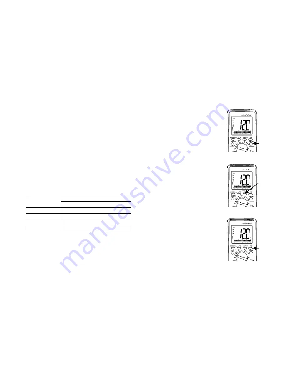
Data Hold/ Backlight
The Data Hold Feature stores the
last reading in memory.
Press the
Data Hold
button
once to hold the present
reading.
Press the
Data Hold
button
again to exit and resume
normal readings.
Press the
Data Hold
button for one
second to turn the backlight on
and press the button a second
time to turn the backlight off.
MAX/
MIN /RS232
Press MAX/MIN to enter, MAX MIN
recording mode. MAX/MIN function is
operative in
manual range only
!
Select the proper range before
activating MAX MIN to ensure that the
MZX/MIN reading will not exceed the
testing range. Press once to select MAX
Press again to select MIN and
press again release MAX/MIN
recording function.
Press this button down for 2 seconds to
select RS232 PC interface mode.
Relative Mode
The relative measurement feature
allows you to make measurements
relative to a stored reference value.
A reference voltage, current, etc.
can be stored and measurements
made in comparison to that value.


