SW833
Installation & Operation Manual
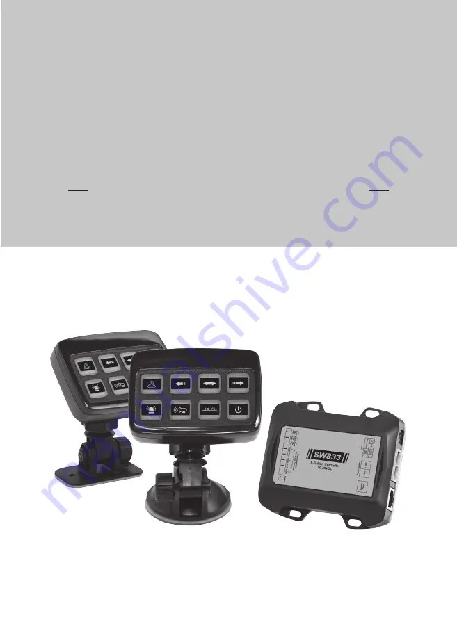
Control Panel 8+2 Outputs - 3 Inputs
Page 1: ...SW833 Installation Operation Manual Control Panel 8 2 Outputs 3 Inputs...
Page 2: ...Mount 4 2 1 3 Power Module 5 2 1 4 Placement of Decals 5 2 2 Wiring 6 2 2 1 Power Module 6 Chapter 3 Programming Operation 3 1 General Operation for Programming Mode 7 3 2 Standby Mode 9 3 3 Default C...
Page 3: ...is product or route any wires in the air bag deployment zone of your vehicle Equipment mounted or located in air bag deployment zones will damage or reduce the effectiveness of the air bag or become a...
Page 4: ...elf drilling Screw x 2 pcs 4 x 15mm Decals x 1 set Manual x 1 pc 1 2 Specifications 1 2 1 Controller Operating Voltage 10 30VDC Operating Temperature 40 C 60 C Dimensions 68 8mm x 95mm x 25 5mm 1 2 2...
Page 5: ...t an angle most convenient to your operation 1 Choose a desired place for installation 2 Press the suction cup to install the controller on the windshield directly Or assemble the adhesive base at the...
Page 6: ...the power module with the four 8 self drilling screws supplied NOTE Always install the power module away from a heat source 1 The controller is shipped without any button decals installed 2 After asse...
Page 7: ...put 1 max 15A Positive Output 2 max 10A Positive Output 3 max 10A Positive Output 4 Positive Output 5 Positive Output 6 Positive Output 7 Positvie Output 8 Power Indicator RJ45 Cable Terminal Block 6...
Page 8: ...B4 for more than 1 second to enter Programming Mode 2 NOTE The indicator light in the upper right corner will flash in single flash for Mode 1 or double flash for Mode 2 Change Setting Value 1 Press B...
Page 9: ...three times and green backlight is ON Automatic Standby Mode default configuration Automatically enter Standby Mode after 15 minutes if no buttons are activated and Input 1 is not activated either Re...
Page 10: ...y pressing B4 for more than 1 second It will turn off all button functions Refer to 3 6 Programming Mode 2 p 19 for detailed information of Standby Mode Configu ration NOTE After entering Standby Mode...
Page 11: ...main warning light will activate B3 grill warning light simultaneously NOTE B3 can be activated only when B1 is activated When B3 is activated turn on Input 2 handbrake will deactivated B3 immediately...
Page 12: ...7 B8 B1 B2 B3 B4 B5 B6 B7 B8 3 4 Scene 1 and Scene 2 Controlled by B5 and B6 Scene Button Combo Scene 1 Under Programming Mode 1 you can set B5 as the start button of Scene 1 While B5 is activated B1...
Page 13: ...d B3 for more than 1 second to exit and save your configu ration B1 B2 B3 B4 B5 B6 B7 B8 B1 B2 B3 B4 B5 B6 B7 B8 B1 B2 B3 B4 B5 B6 B7 B8 3 5 Programming Mode 1 for setting B1 B8 button function Settin...
Page 14: ...al momentary switch Press the switch once to activate B1 and B2 Press the switch once again to deactivate B2 Input 3 is connected to an external on off switch Only when B1 is activated turn on the swi...
Page 15: ...Siren Interlock w o Siren Kill 1 Activate B2 siren will also activate B1 main warning light simultaneously 2 B2 is not affected by Input 2 Siren Interlock w o Siren Kill 1 B2 siren can be activated on...
Page 16: ...rning light simultaneously NOTE B3 can be activated only when B1 is activated 2 When B3 is activated turn on Input 2 handbrake will deactivate B3 immediately NOTE B3 will not revert when Input 2 handb...
Page 17: ...can be activated automatically only when Input 2 handbrake is ON and B1 main warning light is activated Under that circumstance B4 can be turned on off manually Include B5 into Group 1 button combo Wh...
Page 18: ...t switch activated upon the power is ON ON OFF switch 3 Momentary switch 4 5 7 6 2 default Include B6 into Group 1 button combo When B5 B7 and B8 are also included in Group 1 B5 B6 B7 and B8 are mutua...
Page 19: ...Group 3 button combo When B6 and B8 are also included in Group 3 B6 B7 and B8 are mutually exclusive Enter Programming Mode 1 and configure B8 Setting as the following table B8 Setting B8 controls Pos...
Page 20: ...ing 3 After finishing setting press B2 and B4 for more than 1 second to exit and save your configu ration B1 B2 B3 B4 B5 B6 B7 B8 B1 B2 B3 B4 B5 B6 B7 B8 3 6 Programming Mode 2 Setting Example Program...
Page 21: ...d and Input 1 is not activated Manually enter Standby Mode by pressing B4 for more than 1 second Automatically enter Standby Mode after 15 minutes if no buttons are activated and Input 1 is not activa...
Page 22: ...by Input 2 4 2 3 1 default 1 default Traffic arrow can be used when handbrake is ON Connect Input 2 to handbrake 1 If Input 2 is ON Group 1 Group 2 Group 3 are available for activation 2 If Input 2 i...
Page 23: ...Left Arrow 1 default Activate 4 display modes of Indicator Light for Group 1 Group 2 NOTE Group 1 has higher precedence than Group 2 Reset to Factory Default Configuration Under Programming Mode 2 you...
Page 24: ...ive Output 6 and 8 B8 controls Positive Output 8 NOTE Positive Output 7 is permanent positive output 3 8 Button Combo Group 2 If the B5 B6 B7 B8 are configured in the Group 2 they are mutually exclusi...