background image

16

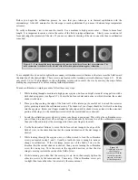
Figure 4-3

A collimated telescope 

should appear 

symmetrical with the 

central obstruction 

centered in the star's

diffraction pattern.

Before  you  begin  the  collimation  process,  be  sure  that  your  telescope  is  in  thermal  equilibrium  with  the 
surroundings.    Allow  45  minutes  for  the  telescope  to  reach  equilibrium  if  you  move  it  between  large  temperature 
extremes.

To  verify  collimation,  view  a  star  near  the  zenith.    Use  a  medium  to  high  power  ocular  — 12mm  to  6mm  focal 
length.  It is important to center a star in the center of the  field to judge collimation.    Slowly cross  in and out of 
focus and judge the symmetry of the star.  If you see a systematic skewing of the star to one side, then re-collimation 
is needed. 

To accomplish this, you need to tighten the secondary collimation screw(s) that move the star across the field toward 
the direction of the skewed light.  These screws are located in the secondary mirror holder (see figure 4-1).    Make 
only  small  1/6  to  1/8  adjustments  to  the  collimation  screws  and  re-center  the  star  by  moving  the  scope  before 
making any improvements or before making further adjustments.

To make collimation a simple procedure, follow these easy steps:

1.

While looking through a medium to high power eyepiece, de-focus a bright star until a ring pattern with a 
dark shadow appears (see figure 4-2). Center the de-focused star and notice in which direction the central 
shadow is skewed. 

2.

Place  your  finger  along  the  edge  of  the  front  cell  of  the  telescope  (be  careful  not  to  touch  the  corrector 
plate), pointing towards the collimation screws. The shadow of your finger should be visible when looking 
into the eyepiece.  Rotate your finger around the tube edge until its shadow is seen closest to the narrowest 
portion of the rings (i.e. the same direction in which the central shadow is skewed).

3.

Locate the collimation screw closest to where your finger is positioned. This will be the collimation screw 
you  will  need  to  adjust  first.  (If  your finger  is  positioned  exactly between  two  of  the  collimation  screws, 
then you will need to adjust the screw opposite where your finger is located).

4.

Use the hand control buttons  to move the de-focused star image to the edge of the 
field of view, in the same direction that the central obstruction of the star image is 
skewed.

5.

While  looking  through  the  eyepiece,  use  an  Allen  wrench  to  turn  the  collimation 
screw  you located in step 2 and 3.  Usually a tenth of a turn is enough to  notice a 
change  in  collimation.    If  the  star  image  moves  out  of  the  field  of  view  in  the 
direction  that  the  central  shadow  is  skewed,  than  you  are  turning  the  collimation 
screw  the  wrong  way.  Turn  the  screw  in  the  opposite  direction,  so  that  the  star 
image is moving towards the center of the field of view.

6.

If  while  turning  you  notice  that  the  screws  get  very  loose,  then  simply  tighten  the 
other  two  screws  by  the  same  amount.    Conversely,  if  the  collimation    screw  gets 
too tight, then loosen the other two screws by the same amount.

Figure 4-2 -- Even though the star pattern appears the same on both sides of focus, they are asymmetric.  The 
dark obstruction is skewed off to the left side of the diffraction pattern indicating poor collimation.

Summary of Contents for EdgeHD 11

Page 1: ...E Ed dg ge eH HD D S Se er ri ie es s INSTRUCTION MANUAL E Ed dg ge eH HD D 8 8 E Ed dg ge eH HD D 9 9 2 25 5 E Ed dg ge eH HD D 1 11 1 E Ed dg ge eH HD D 1 14 4 ...

Page 2: ...80x 555x 660x 840x Lowest Useful Magnification 29x 34x 40x 51x Limiting Stellar Magnitude 14 14 4 14 7 15 3 Resolution Rayleigh 68 arc seconds 59 arc seconds 50 arc seconds 39 arc seconds Dawes Limit 57 arc seconds 49 arc seconds 42 arc seconds 33 arc seconds Light Gathering Power 843x unaided eye 1127x unaided eye 1593x unaided eye 2579x unaided eye Field of View standard eyepiece 85º 8º 67º 48º ...

Page 3: ...ou looked straight through To attach the 1 25 star diagonal onto the 8 optical tube 1 Turn the set screw on the visual back until its tip no longer extends into i e obstructs the inner diameter of the visual back 2 Slide the chrome portion of the star diagonal into the visual back 3 Tighten the set screw on the visual back to hold the star diagonal in place If you wish to change the orientation of...

Page 4: ...lescopes comes with a 9x50 finderscope The specifications for a finderscope stand for the magnification and the aperture in millimeters of the scope So a 9x50 finder magnifies objects nine times and has a 50mm objective lens Finderscope Installation The finderscope must first be mounted in the included quick release bracket then attached to the rear cell of the telescope To install the finderscope...

Page 5: ...sure on the finder so that the adjustment screws are always making contact with the finder To make the alignment process a little easier you should perform this task in the daytime when it is easier to locate objects in the telescope without the finder To align the finder 1 Choose a conspicuous object that is in excess of one mile away This will eliminate any possible parallax effect between the t...

Page 6: ...l system they travel the length of the optical tube three times The optics of an EdgeHD telescopes have Starbright XLT coatings enhanced multi layer coatings on the primary and secondary mirrors for increased reflectivity and a fully coated corrector for the finest anti reflection characteristics Inside the optical tube a black tube extends out from the center hole in the primary mirror This is th...

Page 7: ...st the pull of gravity In doing so any mirror shift is minimized For astronomical observing both visually and photographically this is done by turning the focus knob counterclockwise Mirror Support Clutches The EdgeHD Optical tube is equipped with mirror tension clutches to help support and minimize lateral movement of the primary mirror during astrophotography To use the mirror clutches 1 Use the...

Page 8: ...ultiply by 52 5 Continuing with our example multiply the angular field 9 by 52 5 This produces a linear field width of 47 feet at a distance of one thousand yards The apparent field of each eyepiece that Celestron manufactures is found in the Celestron Accessory Catalog 93685 General Observing Hints When working with any optical instrument there are a few things to remember to ensure you get the b...

Page 9: ...mera bodies The camera must have interchangeable lenses so you can attach it to the telescope and so you can use a variety of lenses for piggyback photography If you can t find a new camera you can purchase a used camera body that is not 100 percent functional The light meter for example does not have to be operational since you will be determining the exposure length manually You also need a cabl...

Page 10: ... a deluxe tele extender 93643 which attaches to the visual back and a T ring for your particular camera make i e Minolta Nikon Pentax etc Because of the high magnifications during eyepiece projection the field of view is quite small which makes it difficult to find and center objects To make the job a little easier align the finder as accurately as possible This allows you to get the object in the...

Page 11: ...osure times listed here should be used as a starting point Always make exposures that are longer and shorter than the recommended time Also take a few photos at each shutter speed This will ensure that you get a good photo It is not uncommon to go through an entire roll of 36 exposures and have only one good shot NOTE Don t expect to record more detail than you can see visually in the eyepiece at ...

Page 12: ...cess 10 Open the shutter using a cable release 11 Monitor your guide star for the duration of the exposure using the buttons on the hand controller to make the needed corrections 12 Close the camera s shutter When getting started use a fast ISO setting to record as much detail in the shortest possible time Metering The EdgeHD telescopes have a fixed aperture and as a result fixed f ratios To prope...

Page 13: ...bed below is the configuration of each F number and the type of object best suited to that kind of imaging The above figure shows how the secondary mirror is removed when using the optional CCD camera for f 2imaging Warning The secondary mirror should never be removed unless installing the optional f 2 lens assembly Adjustments to collimation can easily be made by turning the screws on the top of ...

Page 14: ...ller What is the difference between f 2 and f 10 F 2 has 1 5 the focal length of f 10 That makes the exposure time needed about 25 times shorter than at f 10 the field of view 5 times larger and the object size 1 5 compared to that of f 10 see Table below Telescope Model Standard f 10 Configuration f 2 Configuration Focal Length Speed 8 80 2032mm 16 406 4mm 9 25 93 2350mm 18 5 470mm 11 110 2800mm ...

Page 15: ... the corrector remove the accessories from the rear cell of the telescope Place the telescope in a dust free environment and point it down This will remove the moisture from the telescope tube To minimize the need to clean your telescope replace all lens covers once you have finished using it Since the rear cell is NOT sealed the cover should be placed over the opening when not in use This will pr...

Page 16: ...ot to touch the corrector plate pointing towards the collimation screws The shadow of your finger should be visible when looking into the eyepiece Rotate your finger around the tube edge until its shadow is seen closest to the narrowest portion of the rings i e the same direction in which the central shadow is skewed 3 Locate the collimation screw closest to where your finger is positioned This wi...

Page 17: ...at steps 2 through 6 as described above for the new direction Perfect collimation will yield a star image very symmetrical just inside and outside of focus In addition perfect collimation delivers the optimal optical performance specifications that your telescope is built to achieve If seeing i e air steadiness is turbulent collimation is difficult to judge Wait until a better night if it is turbu...

Page 18: ...llowing focal lengths 4mm 6mm 9mm 12 5mm 15mm 20mm 25mm 32mm and 40mm X Cel This 6 element design allows each X Cel Eyepiece to have 20mm of eye relief 55 field of view and more than 25mm of lens aperture even with the 2 3mm In order to maintain razor sharp color corrected images across its 55 field of view extra low dispersion glass is used for the most highly curved optical elements The excellen...

Page 19: ...es to the rear cell of the telescope As light from the telescope enters the guider most passes straight through to the camera A small portion however is diverted by a prism at an adjustable angle up to the guiding eyepiece This guider has two features not found on other off axis guiders first the prism and eyepiece housing rotate independently of the camera orientation making the acquisition of a ...

Page 20: ...ing or unauthorized repair Further product malfunction or deterioration due to normal wear is not covered by this warranty CELESTRON DISCLAIMS ANY WARRANTIES EXPRESS OR IMPLIED WHETHER OF MERCHANTABILITY OF FITNESS FOR A PARTICULAR USE EXCEPT AS EXPRESSLY SET FORTH HEREIN THE SOLE OBLIGATION OF CELESTRON UNDER THIS LIMITED WARRANTY SHALL BE TO REPAIR OR REPLACE THE COVERED PRODUCT IN ACCORDANCE WI...

Page 21: ... Torrance CA 90503 U S A Tel 310 328 9560 Fax 310 212 5835 Web site at http www celestron com Copyright 2009 Celestron All rights reserved Products or instructions may change without notice or obligation Item 91030 INST 10 00 07 09 ...

Reviews: