CEL-MAR ADA-4010A User Manual Download Page 7

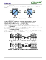
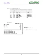
3.3.2. RS485(2W) BUS CONNECTION

Fig 6. Example connection of ADA-4010A to RS485(2W) 2-wire bus and galvanic separation SLAVE device

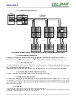
3.3.3. GND TERMINAL CONNECTION

Connection of GND terminals of RS485/422 interfaces, devices connected to RS485/422 bus, should be done in the case of a 

potential difference of the signals grounds on interfaces RS485 / RS422, which prevents proper data transmission.

Cannot connect to the GND terminal - cables screens, PE circuit of electrical installation, signals grounds of other devices.

3.3.4. LINE TERMINATION Rt

The application of Line Termination (terminator) Rt = 120 ohms will reduce electrical reflection in data line at high baud rate. It is not

needed below 9600Bd. Should be used the Line Termination resistor if the distance is over 1000m @ 9600Bd or 700m @ 19200Bd,

and if the disturbance in transmission will appear.
Example connection of resistor Rt are shown on fig.5 & fig.6. Two resistors Rt=120  

W

 , 5%, 0,25W is delivered with ADA-4010A.

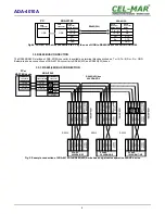
3.3.5. CONNECTION OF RS232 INTERFACE DEVICES

Connections of SLAVE device with RS232 interface to ADA-4040A are shown on fig.5 & fig.6. 

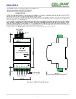
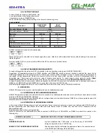
3.4. POWER SUPPLY CONNECTION

To connect power supply to the converter, should have DC power supplies (regulated) output voltage from 10 V= to 30V=, min.

nominal power 2W, e.g. DR-15-24. Power cable from DC power supplies to device can not be longer than 3m. Should connect positive

(+) end of DC power supplies to V+ device terminal and negative (-) end to V- on terminal block. ADA-4010A has protection against

power supply reverse connection. If after power connection the green LED PWR on front panel is not lit, check correctness of power

supply connection (polarisation).

4. ACTIVATION

The converter can be power on after properly connection according to section above.

If   after   connection   power   supply   on   front   panel   will   not   light   green   led   PWR,   check   correctness   of   power   supply   connecting

(polarization). When data is present the LEDs Tx and Rx should blink

7

ADA-4010A

(5) GND

GND

(2) Rx

(3) Tx

RS232 

connector DB-

9F/DCE

Screw 

connector

RS485 / RS422

RS232 

connector

DB-9M/DTE

ADA-I1040

GND (5)

Tx (2)

Rx (3)

Rt

Rx+

Rx-

Tx+/ A

Tx-/ B

RS485(4W) bus
9600Bd/8/O/1

PC or

MASTER device

RS232

SLAVE
2400Bd/8/N/2

SLAVE
19200/Bd/7/N/2

SLAVE
9600Bd/8/E/1

RS232

RS232

Summary of Contents for ADA-4010A

Page 1: ...User Manual ADA 4010A Addressable RS 485 RS 422 to RS 232 Baud Rate Converter 1 io_ada 4010a_v4 02_en ADA 4010A Copyright 2001 2017 CEL MAR sp j...

Page 2: ...CONNECTION OF RS232 INTERFACE DEVICES 7 3 4 POWER SUPPLY CONNECTION 7 4 ACTIVATION 7 4 1 DESCRIPTION OF SIGNALLING LEDS 8 4 2 TROUBLESHOOTING 8 5 CONFIGURATION 8 5 1 CONVERTERS OPERATION MODE 8 5 2 CO...

Page 3: ...ring circuit Do not take the installation or device disassembly if it is turn on It can lead to the electric short circuit and damaging the device The device can not be used for applications that dete...

Page 4: ...port converter supports asynchronous baud rate up to 230 4 kbps through one or two pairs of twisted cable of RS485 422 interface ADA 4010A is equipped with screw terminal block for connection of RS232...

Page 5: ...n TS 35 DIN35 rail To install the converter should be mounted on the rail upper part of the cover then press bottom part to hear characteristic Click sound 3 2 COMPUTER CONNECTION ADA 4010A can be con...

Page 6: ...ection of ADA 4010A to RS485 4W 4 wire bus and galvanic separation SLAVE device 6 ADA 4010A 5 GND GND 2 Rx 3 Tx RS232 connector DB 9F DCE Screw connector RS485 RS422 RS485 4W bus 9600Bd 8 O 1 RS232 co...

Page 7: ...Connections of SLAVE device with RS232 interface to ADA 4040A are shown on fig 5 fig 6 3 4 POWER SUPPLY CONNECTION To connect power supply to the converter should have DC power supplies regulated outp...

Page 8: ...e use a small flat screwdriver All available adjusting the SW1 switch are shown in table below Operation modes SW1 1 SW1 2 Mode OFF OFF Run ON OFF Configuration OFF ON Factory default Turning OFF and...

Page 9: ...S232 RS485 RS422 interfaces can be set a for RS232 interface signal DE Off disabled continuously signal DE Toggle RTS is setted ON during data transmission and OFF after end data transmission signal D...

Page 10: ...rrect message Fig 8 Selection of firmware file During loading software the yellow LED located beside SW1 micro switch will blink showing data flow to ADA 4010A If the software loaded correctly yellow...

Page 11: ...counters in the memory of the converter press Delete transmission errors In case of parity errors or frame errors should be checked the ADA 4010A converter s configuration and correctness connection...

Page 12: ...erefore converter can operate at full duplex mode on RS 422 and RS 485 RS2 4 wire bus Additionally can be set data flow control for RS485 RS422 and RS232 interfaces according to pt CONFIGURATION BY TH...

Page 13: ...Data Terminal Ready Looped with DSR GND SG Signal ground GND 9 VERSIONS ADA 4010A Order example Product Symbol ADA 4010A 23 3 23 3 way galvanic isolation 1kV 3 cover without inlets plug in screw term...

Page 14: ...d length of power cable up to 3m Power 2W Protection from reverse power polarization YES Galvanic Isolation 2 way or 3 way on the level 1kV or 3kV DC between power circuit and RS 485 422 signal line O...

Page 15: ...15 ADA 4010A...

Page 16: ...ransmission converters with interface RS232 RS485 RS422 USB Ethernet Wi Fi Current Loop Fibre Optic Converters and other Please contact us to tell how you like our products and how we can satisfy you...

Reviews: