


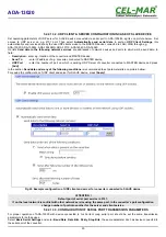


1. From menu
Configuration
select
Users,
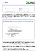
2. In section
Configure Users
, select added user eg.
admin
,
3. Will open the page
User Configuration
– admin, where are sections:
A/
User Configuration
– possibility of rename user and password,
B/
User Access
- method of access to converter from the network:
Allow command line access
– access using the Command Line Interface -
telnet
,
Allow web interface access
– access using the internet browser.
C/
User Permissions -
user permissions to configuration and management of the ADA-13040MG converter, where are options:
None
- no permission,
Read -
permission to read,
Read Self -
permission to read own settings, but not other users.
Read/Write
- full permission to read and write the setting.
Read/Write Self -
permission to read and write own setting, but not other users.
Read All/Write Self -
permission to read the setting for all users and modify only own setting (not other users).
Execute -
permission to execute (start).
4. All changes are saved by pressing
[Apply]
.
5.2.5. MANAGEMENT
In menu
Management
are two options:
-
Serial Ports
-
Connections
5.2.5.1. SERIAL PORT MANAGEMENT
Section
Serial Ports
allows to identification connections/disconnection to the serial port of the converter through the network.
5.2.5.2. CONNECTIONS MANAGEMENT
Section
Connections
allows to identification connections/disconnection to the converter through the network.
5.2.6. ADMINISTRATION
The menu
Administration
allows :
–
to delete/upload files with Java applet,
–
to backup/restore configuration of converter,
–
to update Firmware,
–
to restore the factory default settings,
–
to display system details information,
–
to reboot the converter.
5.2.6.1. FILE MANAGEMENT
Section
File Management
enables upload and delete Web provided by manufacturer. Uploaded index.htm or index.html allows to
automatically run the page in the web browser after entering
http://address-ip-convertera/FS/WEB/index.htm
and login to
ADA-
13020.
5.2.6.2. BACKUP & RESTORE CONFIGURATION
Section
Backup/Restore
enables backup to file or restore from file the user configuration of the converter.
5.2.6.3. FIRMWARE UPDATE
Section
Update Firmware
enables to make the update firmware from the file. Firstly should be done update the POST software before
updating the firmware – more details available on the web page
5.2.6.4. FACTORY DEFAULT SETTINGS
The converter was configured by the manufacturer.
To restore factory default settings, select from menu
Factory Default Settings
. After that the converter will automatically reboot.
5.2.6.5. SYSTEM INFORMATION
Section
System Information
displays:
-
General
– device model, MAC address, firmware version, Boot version, POST version and more.
-
GPIO
– not applicable in ADA-13020.
-
Serial
– port description, current settings of serial port, status of controlling lines and the statistics data transfer through the serial
port.
-
Network
– show statistics of ETHERNET interface for IP, TCP, UDP, ICM protocols.
5.2.6.6. REBOOT
Section
Reboot
allows making software reset of ADA-13020. Pressing [
Reboot
] will start rebooting of server during 1 min.
5.2.6.7. LOGOUT – ENDING MANAGEMENT AND CONFIGURATION
After completion of the configuration or administration should be pressing
Logout
on left panel – logout from www server of ADA-
13020 converter.
22
ADA-13020


