


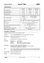


CEDES
cegard
TM
/Max
Operation Manual
14
part no. 101 232
© CEDES
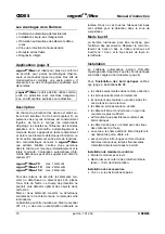
Operation
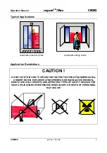
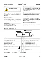
Danger 120 / 240 Volts
Disconnect power before open-
ing the control unit!
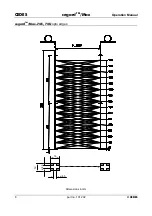
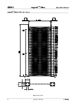
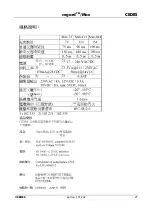
The diagram in the control unit on page 5 (picture
and
)
explain correct connection and opera-
tion.
Buzzer
ON / OFF using switch S as desired. Automatic
calibration is activated, if switched off.
Jumper JP1
Muting of elements is active = JP1 set
No muting allowed = JP1 removed
Hold time of relay
Hold time of the relay can be delayed after the
protective area is free. Delay time is adjustable
with the potentiometer 0 ... 10 s . Default is 0 s.
Test input (optional)
Only for control unit part No. 102 335.
Input 24 VDC = normal operation
Input 0 VDC = test, light curtain inactive
Time of negative test pulse is min. 300 ms.
Rise time of relay after test is max. 200 ms.
Cleaning of opto edges
Use soapy water only. Any use of scratching or
inappropriate cleaning solvents may cause loss of
range or failure.
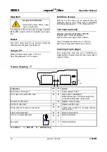
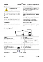
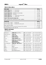
Trouble Shooting
OU
T
PO
W
E
R
EMITTER (E)
RECEIVER (R)
JP
1
0 ... 10s
Indication
green yellow
Action
No function, door open
Power supply? Fuse?
Door open, free protective area
Obstruction? Installation?
EMC-interference? Protective earth (PE)
connection? Defective control unit?
Receiver R defective?
Replace receiver edge
Emitter E defective?
Replace emitter edge
R & E defective? loose connections?
Control unit, connect E / R-edge with pro-
tective earth?
Light curtain blocked?
Remove obstruction
Person or object detected
Normal operation
No object
Normal operation
=
LED on
=
LED off
=
LED flashing


