


12
3.3 C
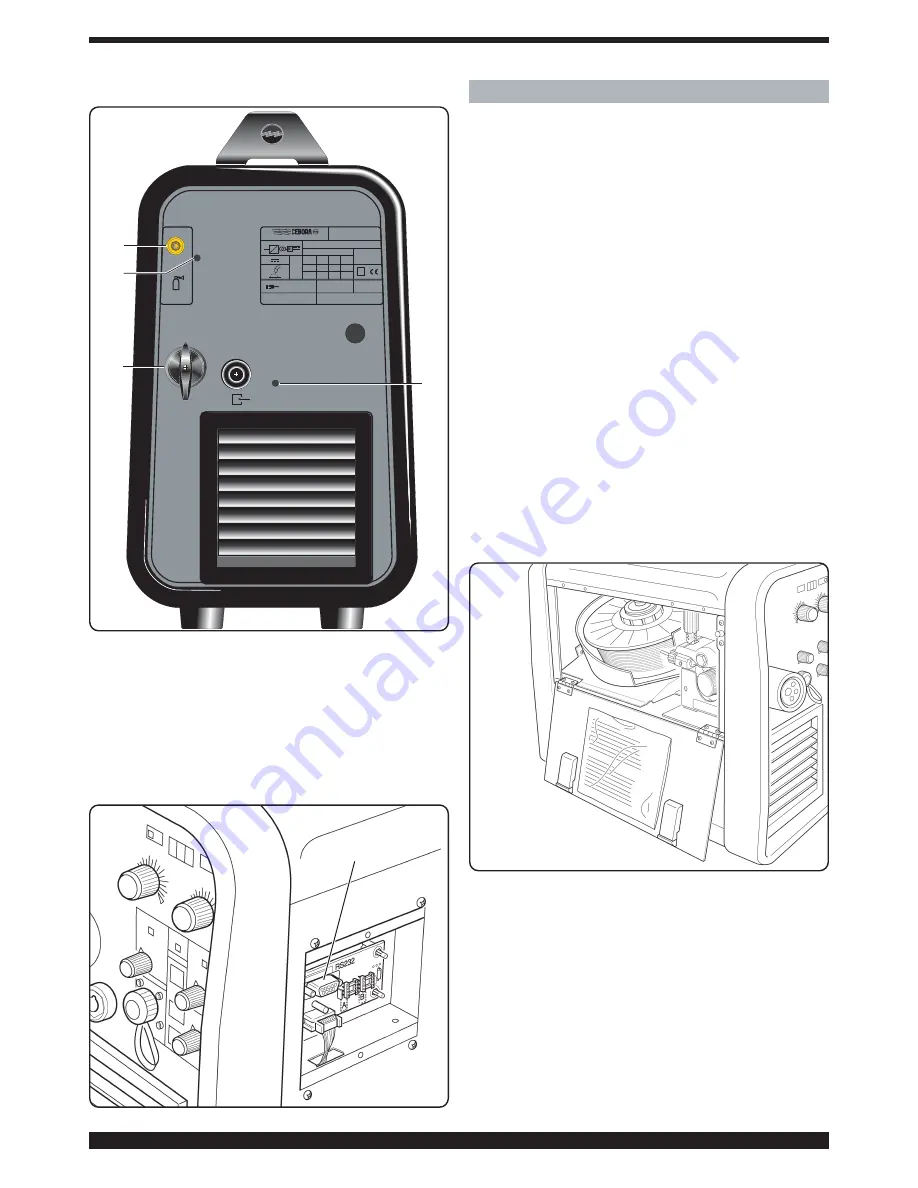
CONTROLS O
ON TTHE R
REAR P
PANEL
T - G
Gas hhose ffitting.
U-S
Switch.
Turns the machine on and off.
V- P
Points ffor aattaching tthe 115Kg ccoil kkit A
Art. 1129
3.4 C
CONNECTOR TTYPE D
DB9 ((RS 2232) (Fig. 3)
To be used for updating the microprocessor programs.
4 W
WELDING
4.1 S
Start-uup
Make sure that the wire diameter corresponds to the
diameter indicated on the wire feeder roller, and that the
selected program is compatible with the material and
type of gas. Use wire feeder rollers with a "U"-shaped
groove for aluminum wires, and with a "V"-shaped groove
for other wires.
4.1.1 C
Connecting tthe ggas hhose
The gas cylinder must be equipped with a pressure regu-
lator and flow gauge.
If the cylinder is placed on the cylinder shelf of the wire
feeder, it must be fastened using the chain provided.
Connect the gas hose leaving the rear of the machine to
the pressure regulator, only after positioning the cylinder.
The gas flow must be adjusted to approximately 8-10
liters per minute.
4.2 TTHE M
MACHINE IIS R
READY TTO W
WELD
When using the Pull-2003 type torch, follow the instruc-
tions enclosed with the torch.
• Connect the earth clamp to the workpiece.
• Set the switch U to 1.
• Choose the program to be used from the list provided
in an envelope on the mobile side panel (Fig. 4).
• Display the number corresponding to the program on
display Q using the keys O and R.
• If a pulsed synergic program is used, turn the knob B
until the display Q shows the thickness you will be using.
At the same time the display G shows the current for the
selected thickness.
• If a synergic program is used, make sure that the indi-
cator of the knobs I and P show the message "SYNER-
GIC" and the scale zero, respectively.
• Remove the gas nozzle.
• Unscrew the contact tip.
• Insert the wire in the wire liner of the torch, making sure
that it is inside the roller groove and that the roller is in the
correct position. Then close the door.
IP 23C
15 /14,7 -200 /24
A
V
A
V
X
(40°C)
I
2
U
2
60
%
35
%
100
%
160
A
200
A
145
A
22
V
24
V
21,2
V
U
0
64
V
U 230 50/60
1
V
Hz
I
1
max =
32
I
20
A
1
A
eff
=
1~
f
1
f
2
MADE IN ITALY
Via A.Costa, 24 - 40057-Cadriano-Bologna-Italy
®
EN 60974-1
EN 50199
Nº
S
MIG 2035/M
PULSE
Art.
285
V
0
1
T
V
U
V
Fig. 2
Fig. 4
W
Fig. 3


