


CEBORA S.p.A.
13
3.302.089
31/05/02
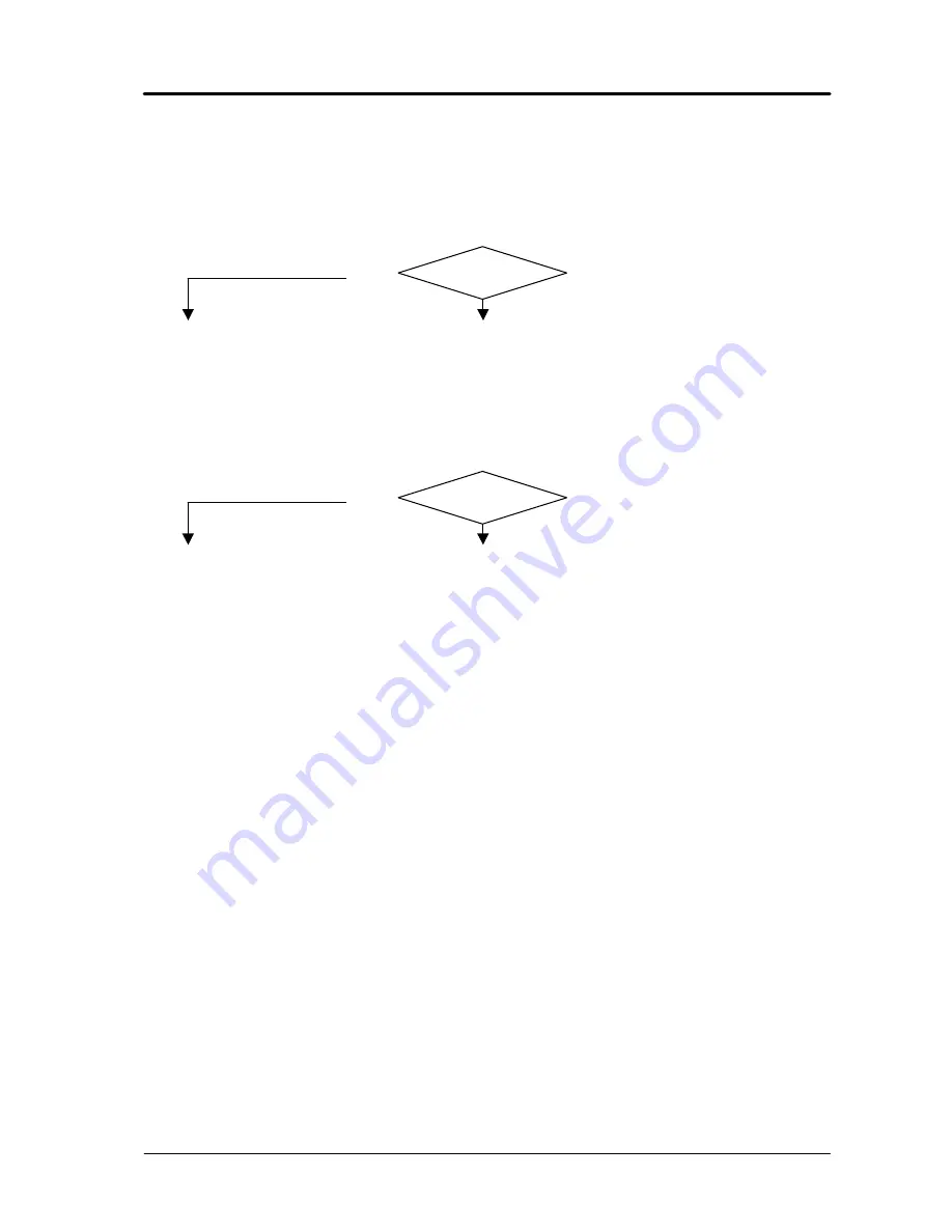
Correct?
Correct?
3.3.5
- No gas flows from the torch.
SOLENOID VALVE (20) TEST.
q
Solenoid valve (20) terminals = +230 Vac with torch button pressed (with mains at either 115
or 230 Vac). The solenoid valve opening time depends on the post-gas time and testing
conditions.
NO
YES
♦
With power source off, make sure the resistance between the terminals of solenoid
valve (20) = approximately 2500 ohm. If > Mohm (winding broken), replace the
solenoid valve (20).
♦
Replace solenoid valve (20).
SOLENOID VALVE (20) COMMAND TEST.
q
HF board (22), connector J1, terminals 7 (+) and 1 (-) = +13 Vdc, with start button pressed.
NO
YES
♦
Check the wiring between solenoid valve (20), connector J2 on HF board (22) and
fan (15).
♦
With power source off, make sure the resistance between the terminals of solenoid
valve (20) = approximately 2500 ohm. If 0 ohm (short circuit), replace the
solenoid valve (20) and HF board (22).
♦
Make sure that the supply voltage on the fan (15) is correct, see par. 3.3.2.
♦
Replace the HF board (22).
♦
Check the wiring between connectors J1 board HF (22) and CN2 panel board (31).
♦
Make sure that the power supply to panel board (31) is correct, see par. 3.3.1, and that the
start command is working properly, see par. 3.3.4.
♦
Replace the panel (31) and/or HF (22) boards.
♦
Make sure there are no occlusions in the gas hoses of the power source.
♦
Check the presence of gas at the power supply fitting (B), and make sure that the pressure and
air flow in the intake line comply with the specified values (see Instructions Manual).
♦
Make sure that the pressure regulator (E) and pressure gauge (F) are working properly;
replace if defective.


