


6.4 Electrical Installation for Bravo 10 shelf
6.4.1 Pre requisites
•
The sub-rack have markings for all terminations.
•
All cables shall be rated at Min 90 deg C.
•
Electrical terminations shall be tightened with 5 Nm.
•
All connection screws are M5 x 12 mm.
•
DC Input - Common (per shelf), check DC polarity.
•
AC Input / AC output - Common (per shelf), check AC phase angle.
•
Wire all positions in the sub-rack for future expansion.
6.4.2 Terminations
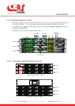
6.4.2.1 EPC Version
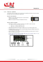
Inview Slot
Terminals
(Refer to section
DC -
DC +
AC OUT
AC IN
L1
PE
L2 (AC IN)
(AC OUT) L2
N
N
PE
L1
Bravo 10 - 48/120 - Shelf Rear Details
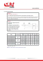
6.4.2.2 REG Version (No AC In)
Inview Slot
Terminals
(Refer to section
DC -
DC +
AC OUT
PE and Neutral bonding
L1
L2 (AC Out)
Grounding
Electrode
Terminal
N PE
Bravo 10 - 48/120 - Shelf Rear Details - REG (No AC Input)
Note:
In REG version, a copper plate is placed between PE and Neutral. Also, ground should be connected to Grounding
electrode terminal using 10-24 inch nut of torque 3.2 to 4.8 ft-lb.
System Installation
21
- Bravo 10 - 48/120 - User manual - v1.1
Summary of Contents for BRAVO 10 - 48/120
Page 59: ......