


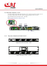
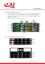


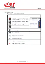


6.4.8 Bravo 10 System with Inview S - Connections
1. Connect module shelf
RJ45 port
and Inview S
CE+T COM
port using RJ45 straight cable.
2. Connect power to
Inview S
from auxiliary power supply kit.
Module Shelf
Auxiliary Power
supply kit
(12 V DC)
Inview S
RJ45
CE+T COM
Power
RJ45 Cable
1
2
To know more about Inview S terminal details, refer to section 5.2.3, page 17.
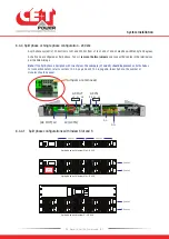
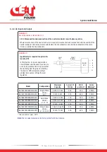
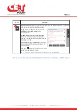
6.4.9 Signalling
Each shelf comprise of 8 and 6 pin connector, Remote ON/OFF and ETH port for communication. The PCB at the bottom
of the rear shelf is for Inview Slot. It can only be accessed if Inview Slot connected to that shelf.
(6 Pin) BUS B
(8 Pin) BUS A
ON/OFF
(CE+T COM port)
Remote
To Inview S
K1
K2
NO
NO
NC
NC
C
C
Power
PE
D1 D2
CAN
Modbus
(RS485)
Inview Slot
Terminals
1 2 3
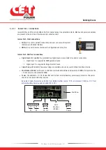
6.4.9.1 Remote ON/OFF
The shelf is by default equipped with a connection between pin 3 and 2. If remote ON/OFF is not used the strap shall
remain in all connected shelves. Should the remote ON/OFF be used, all straps must be removed and in one (1) shelf
replaced with a changeover contact or emergency button.
•
The remote ON/OFF switch the output AC OFF.
•
Input AC and input DC is not affected by the remote ON/OFF.
System Installation
27
- Bravo 10 - 48/120 - User manual - v1.1
Summary of Contents for BRAVO 10 - 48/120
Page 59: ......