background image

Profiled handle 

with end caps

Profiled handle 

fixings cover

Box section 

back-plate

Box section 

cover

End caps

Handle

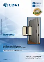
BO600RP

2500 mm

1

1

1

1

2

1

BO600RPSTD

2190 mm

1

1

1

1

2

1

BO600RP3V

2500 mm

1

1

1

1

2

1

EN

BO600RP

Vertical retrofit housing 

Product Details

2] INFORMATION & RECOMMENDATIONS

Power Considerations

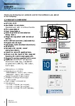
The  handle  is  designed  to  house  electromagnets 

with  a  holding  force  of  300Kg  each.  These 

units  can  be  supplied  by  either  12Vdc  or  24Vdc 

depending  upon  your  preferred  choice  (48v 

supplied  on  special  request).  The  current  required 

depends  on  the  amount  of  electromagnetic  locks, 

and  the  voltage  chosen  –  please  see  Technical 

Specification,  and  ensure  you  have  allocated 

sufficient  power  to  BO600RP  (2500mm  housing 

with  2  magnetic  locks)  would  require:  PSU12/2 

or ARD2/12 at 12Vdc PSU24/1 or ARD24 at 24Vdc.

General Advice

The 2 parts of the architectural housing are designed 

to be surface mounted on the door and frame, where 

they  should  be  parallel  when  the  door  is  closed. 

If there is a rebate, then it will be necessary to pack out 

the lower part to be parallel to the other (Aluminium 

rail spacer, Ref:  REO). You can also use the PRP800 

(Reinforcement section)  or ALMA (Aluminium Cable 

tray) to reinforce the housing mounting.

Wiring

Plan  your  cable  routes  before  commencing 

installation.  We  recommend  a  maximum  distance 

of 10m from the power supply to the electromagnetic 

locks    (to  prevent  volt  drop).  If  the  distance 

is  greater,  then  make  sure  you  have  increased 

the cross section of the cable to compensate.

Information

The  electromagnets  are  pre-fitted  within  the  lock 

section.  The  armature  plates  are  pre-fitted  within 

the architectural handle. Both sections are supplied 

with end caps.

Handle

You must secure the handle with the 2 screws which 

comes with the retrofit housing.

  INSTALLATION MANUAL

3

cdvi.com

cdvigroup.com

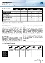
BO600RP

2500MM

BO600RPSTD

2190MM

BO600RP3V

2500MM

BO600RPOPTION

2500MM

Number of 300Kg magnets

2

2

3

2

Lock section with cover

1

1

1

1

Architectural handle 

with fixing cover

1

1

1

1

End caps for handle

2

2

2

2

End caps for lock section

2

2

2

2

RAL colour (option)

-

-

Cut to size

-

-

3] PACKAGE CONTENTS

Summary of Contents for BO600RP

Page 1: ...ION Bandeau architectural vertical Gamme Verrouillage Gamme Verrouillage INSTALLATION MANUAL Vertical retrofit housing Range Locking devices FRANCAIS FR ENGLISH EN V oir conditions de garantie vie lim...

Page 2: ...ng supplied with cover Options Aluminium rail spacers Aluminium cable tray Installation on glass door UBK25 RAL colour Cut to size Holding force 2 x 300kg Dimensions L x W x D BO600RPSTD 2190 x 105 x...

Page 3: ...n the door is closed If there is a rebate then it will be necessary to pack out the lower part to be parallel to the other Aluminium rail spacer Ref REO You can also use the PRP800 Reinforcement secti...

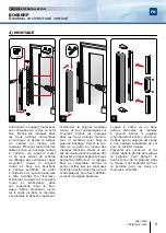
Page 4: ...e the assembly tighten all fixings and protect the handle fixing section by fitting the cover and end caps 1 Cut the top cover unit into 2 pieces Double check the length of each section of top cover b...

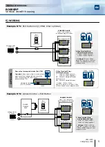
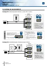
Page 5: ...12Vdc or 24Vdc negative NC Contact Normally Closed COM Common NO Contact Normally Open Voltage 12Vdc or 24Vdc Place the jumpers to select 12Vdc or 24Vdc supply to your magnetic locks 5 Way Terminal St...

Page 6: ...mer To obtain full details of this warranty and to register the product to commence the Limited Lifetime Warranty complete the enclosed registration card and return it either by e mail or post to the...

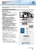
Page 7: ...echnique apr s montage Options Rehausses en aluminium moulures en aluminium pose sur porte en verre R f UBK25 teinte RAL coupe Force du bandeau 2 x 300 kg Dimensions L x l x P BO600RPSTD 2190 x 105 x...

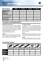
Page 8: ...se et son alimentation Si cette distance est sup rieure pr voir le c ble n cessaire l installation Conseils d utilisation Le bandeau s installe sur des portes en tirant et affleurantes un ou deux vant...

Page 9: ...s son logement 1 Coupez le cache vis en deux parties distinctes de mani re pouvoir ins rer la poign e encombrement environ 250 mm V rifiez que la poign e est situ e une hauteur accaptable du sol pour...

Page 10: ...4V DC NC Contact Normalement Ferm COM Commun NO Contact Normalement Ouvert Alimentation 12 V DC ou 24 V DC En fonction du placement des cavaliers vous alimentez votre ventouse en 12 V DC ou en 24 V DC...

Page 11: ...aleur du produit La responsabilit de CDVI ne peut tre engag e aupr s de l acheteur installateur client final ou qui que ce soit lors de dommages cons cutifs des imperfections ou mauvais fonctionnement...

Page 12: ...12 0 5 22 48 09 40 Fax 212 0 5 22 48 34 69 CDVI SWEDEN SWEDEN DENMARK NORWAY FINLAND Phone 46 0 31 760 19 30 Fax 46 0 31 748 09 30 CDVI UK UNITED KINGDOM IRELAND Phone 44 0 1628 531300 Fax 44 0 1628 5...

Reviews: