background image


Quadrature Devices 

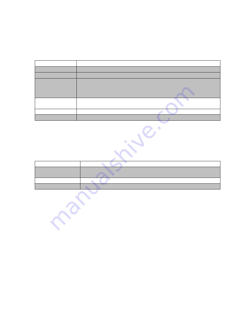
By default, channels are set up in quadrature mode, which provides a real-time display 
of the current indicator’s measurement. The following settings are only available for 
quadrature channels: 

Setting 

Notes 

Encoder 
Resolution 

Set the Encoder Resolution of the device (for example .00005” or .0001”).


Encoder Unit Type 

Selects the unit type of the encoder glass scale (Inch or Metric).


Hold 

Turns on/off Hold mode, under “Gage Functions”, for this channel. This 
setting can be accessed by pressing the “Hold” button for the current 
channel on the main screen. 

Hold Mode 

If Hold is enabled, this setting selects between the available Hold modes: 
Min, Max, and Freeze. Max, and Freeze. 

Resolution 

Sets the display resolution of the remote display. 

Show Min/Max 

Enables display of min and max readings in addition to the readout value. 


Digimatic Devices 

Channels can also be set up to read output from Digimatic devices. These devices need to 
be polled for their current data. The following settings are only available for Digimatic 
channels: 

Setting 

Notes 

Log on Request 

If enabled, a time stamped entry will be made to the data log every time 
the data is refreshed manually. 

Auto Request 

Enables/Disables automatic data refresh. 

Request Interval (s) 

Sets the data update interval if Auto Request is enabled. 


External Data Connection 

The remote display supports data connections over both USB and RS-232 communications. 

PC USB Connection 

The device may work with older operating systems but only Windows 7 and 8 are supported 
by the manufacturer. When connecting the Remote Display to a host computer over USB, 
the Remote Display will function as a Virtual COM Port (VCP), which emulates a standard 
RS-232 serial connection. To use this feature, follow these steps to establish communication 
between the display and the host PC. 
 
(These instructions assume that host computer is running Windows 7): 


1.  Install the USB drivers that were bundled with the Remote Display. Be sure to install 

the correct drivers for the version of Windows (32-bit or 64-bit) that you are installing 
on. This can be determined by opening the System properties (Control Panel -> 

Summary of Contents for EMS 4

Page 1: ...1 Remote Display User Manual ...

Page 2: ...USB Connection 9 RS 232 Serial Connection 12 Communication Protocol 12 Parameter List 13 File Transfer from Tablet 14 Transfer via SD Card microSD cards can be purchased from your local computer store 14 Transfer via USB Connection 16 Transfer to Cloud Storage 16 Supplemental Information 18 Digimatic Interface 18 Signal Timing 18 Data Ordering 19 Digimatic Data Format 20 Quadrature Signal Format 2...

Page 3: ...ry intuitive and user friendly way to configure and monitor several gages at once Connecting the Remote Display to a computer or other serial device makes data collection and statistical process control SPC simple and easy Features Simultaneous connection of up to four measurement instruments Both Digimatic or raw quadrature devices supported on all four ports Nearly any Digimatic gage regardless ...

Page 4: ...le for triggering updates on all connected channels Four 10 pin gage channel connectors The rear panel of the Remote Display Mux Box houses the power and communication interface connectors as well as a power indicator LED 1 USB Type A port for connecting the supplied Android tablet 2 USB Type B port for connection to a computer or laptop 3 RS 232 port for connection to external data consumers 4 Po...

Page 5: ... start reporting counts immediately after connecting Confirm this by moving the spindle of the probe 5 Plug the device with Digimatic output into channel 2 To configure channel 2 for Digimatic communication mode long press on the CH 02 Channel 2 Properties page will appear on the tablet Scroll down to the setting for Gage Type then make sure Digimatic is selected Press the back button on the table...

Page 6: ...Error ensure that the Remote Display is powered using the external AC adaptor and that the Android tablet is connected to the USB A plug on the back of the display Refer to Hardware Overview section for more information about identifying the connectors Main Display The main screen of the Remote Display application is shown below As channels are enabled and disabled the screen will update dynamical...

Page 7: ...es Channel Enabled Enables Disables channel Disabling a channel will hide it from the main display Gage Type Selects the channel function between Quadrature and Digimatic modes Unit Type Selects measurement unit between Inch Millimeter and Hidden Mode Selects indication mode between Incremental default Absolute and Total Indicated Runout TIR TIR is only available for Quadrature Devices Absolute Of...

Page 8: ...t data The following settings are only available for Digimatic channels Setting Notes Log on Request If enabled a time stamped entry will be made to the data log every time the data is refreshed manually Auto Request Enables Disables automatic data refresh Request Interval s Sets the data update interval if Auto Request is enabled External Data Connection The remote display supports data connectio...

Page 9: ...ded application to use with the Remote Display You can download it using the following link http www chiark greenend org uk sgtatham putty To install PuTTY follow this procedure 1 Once on the Putty website click on Download PuTTY 2 Scroll down to MSI Windows Installer Flick on the appropriate 32 or 64 bit version of the msi program and install the program 3 When the nstaller finishes downloading d...

Page 10: ...10 ...

Page 11: ...nect to the Remote Display Successful connection will open a blank terminal window 5 To test the connection press the Enter key The message No such command should appear on the screen If nothing is displayed on the terminal screen disconnect the device cycle power and then repeat this procedure 6 Refer to the Communication Protocol section below for a list of available commands ...

Page 12: ...ices available When searching ensure that the device is compatible with the Operating System version that is being used on the computer Communication Protocol The following list summarizes the serial commands available for exchanging data with the Remote Display Mux Box These commands apply to both the RS 232 and PC USB communication modes Type Enter or Return after command Command Description A P...

Page 13: ...008 Hold Mode 0 Freeze 1 Min 2 Max p009 Tolerance Enable 0 Disabled 1 Enabled p910 Upper Tolerance Enter value without decimal Ex 012345 0 12345 p911 p914 Lower Tolerance Absolute Offset Enter value without decimal Ex 012345 0 12345 Enter value without decimal Ex 012345 0 12345 p016 Gage Type 0 Digimatic 1 Encoder p017 Glass Type encoders only 1 Inches 2 Millimeters p018 Base Multiplier one encode...

Page 14: ...puter store Files can be saved to the external microSD Card and transferred to any PC with a microSD card reader To copy logging data to the card from within the Remote Display Android application swipe right from the left side of the screen or press the back button to show the application menu and click View Data Logs From this screen click the Copy to SD button The application will automatically...

Page 15: ...PC over USB To do this connect the tablet to a PC over USB and wait for Windows to install the driver for the tablet Once the drivers are installed successfully open a new Explorer window and navigate to My Computer The tablet should appear under the list of drives and devices as shown below The data logs for the Remote Display application will be found in the following location Internal Storage L...

Page 16: ...Display application and return to the View Data Logs screen as shown previously Click the Edit button and choose the channel number of the data log that you want to transfer This will open the Spreadsheet application Click Save As on the top header if this is not displayed click on the S button in the top left side of the application to show it and then click on Cloud Storage at the top of the dia...

Page 17: ...17 Find the preferred cloud storage service and follow the instructions to save the logs ...

Page 18: ...andard 10 pin Digimatic connector pinout Pin No Name Function 1 GND Signal Ground 2 DATA 1 Outlet data 3 CLOCK Clock 4 RDY READY Data transmission ready 5 REQUEST Data output request from external device 6 NC 7 NC 8 5V 5V Input terminal 9 5V 5V Input terminal 10 GND Frame ground ...

Page 19: ...gage then sends data the DATA signal that is clocked by the CK line In this case the data ready RDY line is not applicable Figure 1 2 shows a timing chart for the case where the gage asserts its active low data ready signal RDY to indicate that a new gage measurement is available This triggers a data transfer that is initiated by the host device Data Ordering ...

Page 20: ...20 ...

Page 21: ...21 Digimatic Data Format ...

Page 22: ...cifications will not guarantee proper functionality of quadrature devices Expected Quadrature Signal Quadrature Conditioning Circuit The following circuit is used internally in the Remote Display to condition the quadrature signals for decoding Ensure that any quadrature devices connected to the Remote Display are compatible with the electrical specifications of this circuit ...

Page 23: ...of Windows 8 or Windows 8 1 may experience difficulty installing unsigned drivers The following procedure can be used to install these drivers 1 From the desktop move the cursor to the right side of the screen to show the Charms menu Click on Settings ...

Page 24: ...24 Click on Change PC Settings at the bottom to open the control panel Select Update recovery from the list of options ...

Page 25: ...25 4 Select Recovery from the resulting menu and then click on the Restart now button under the Advanced Startup heading 5 From this menu click on Troubleshoot ...

Page 26: ...26 6 Select Advanced Options from the Troubleshoot menu 7 Select Startup Settings ...

Page 27: ...ess F7 on the keyboard to select Disable driver signature enforcement 9 When Windows loads it will not look different than usual but it will be possible to install unsigned drivers Follow the typical driver installation process to install the drivers Be sure to reboot the computer normally immediately after installing the drivers END ...

Reviews: