background image

CD Automation srl 

CD3000E-3PH from 25A to 500A 

User’s Manual 

46 


12.7


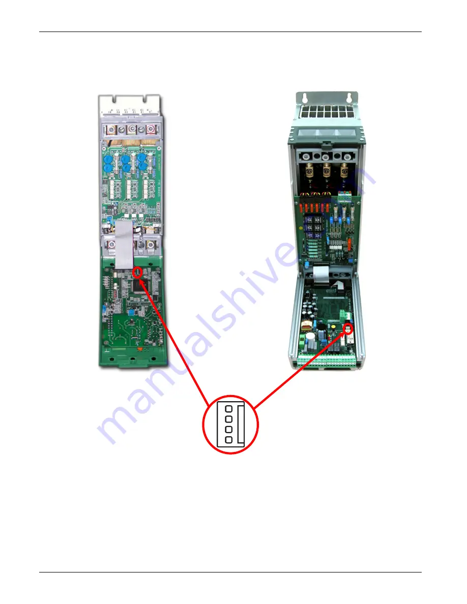
PG Connector 

The PG Connector is used to configure the thyristor unit with the configuration software and with the 
programming cable. 
The programming cable is not included. 


Connettore PG


Summary of Contents for CD3000 E-3PH

Page 1: ... S r l Via Picasso 34 36 20025 Legnano MI ITALY Tel 39 0331 577479 Fax 39 0331 579479 E Mail info cdautomation com WEB www cdautomation com CD3000E 3PH Thyristor Unit USER S MANUAL Rev 02 2015 00007 from 25A to 600A ...

Page 2: ......

Page 3: ...6 2 Dimensions and Fixing holes 15 6 3 Removing the cover 16 7 Wiring instructions 17 7 1 Wiring details 17 7 2 Power Terminals 19 7 3 Command Terminals Size S09 20 7 4 Diagram of control connection Size S09 21 7 5 Command Terminals Size S11 S13 S14 22 7 6 Diagram of control connection Size S11 S13 S14 23 8 Power output features 24 8 1 Derating curve 24 8 2 Cooling fans 24 9 Led status and Alarms ...

Page 4: ...ts 43 12 5 Digital Input 44 12 6 Digital Output 45 12 7 PG Connector 46 12 8 RS485 Serial Port 47 13 MODBUS communication 48 13 1 MODBUS RTU Protocol 48 13 2 Message Format 48 13 3 Read Holding Registers 50 13 4 Preset Multiple Registers 50 13 5 Error and exception responses 51 13 6 Address Configuration 51 14 Configuration Parameters 52 14 1 Operator Menu 52 14 2 Hardware Menu 54 14 3 Setup Menu ...

Page 5: ...ows the qualified people to work in safety Protection Protection Protezione The unit have IP20 protection rating as defined by the specific international Is necessary consider the place of installation Earth Terre Messa a terra For safety the Thyristor unit with isolated heat sink must be connected to earth Earth impedance should be correspondent to local earth regulation Periodically the earth ef...

Page 6: ...ll suggestions contained in this manual are respected In respect to a good Engineering practice all inductive loads like solenoids contactor coils should have a filter in parallel Emissions Emission Emissioni All solid state power controllers emit a certain amount of radio frequency energy because of the fast switching of the power devices The CD Automation s Thyristor unit are in accord with the ...

Page 7: ...etely digital and is based on a powerful microprocessor with high performance that allow the use in different ways Single cycle Burst Firing with soft start and current limit Delayed triggering Phase Angle with soft start and current limit On same unit can be used different feed back that define the control mode Voltage Current Power VxI External 0 10Vdc On same unit can be used different input 4 ...

Page 8: ...nd without stop the production process Technical Specification Use in Local Remote Set Point Ramp UP Down Scroll selection of Set point Power output Current Voltage Display indication for Heater Break alarm SCR short circuit Password for configuration parameters Plug in connector on front to use software configurator Retransmission 4 20mA or 0 10Vdc of one of these parameters Power PV Current Volt...

Page 9: ...re launch the program and follow the instructions on the screen To connect the unit at the PC it s necessary use the USB TTL converter connected between the unit and the USB port of the PC USB TTL converter need a driver to work properly you can find it from our site Is available a full programmer kit composed by USB TTL converter Two cable Thyristor configurator software USB driver With the CD RS...

Page 10: ...s than the MAX voltage of CD3000E see par 4 2 Verify the Order Code see par 5 2 3 Verify the Installation see par 6 4 Verify the Diagram of control connection All auxiliary connections must be done in line with wirings on this manual Verify that there isn t a short circuit on the load see par 7 4 5 Supply the Electronic boards see Order Code 6 If not specified in the Order Code Set the Load Voltag...

Page 11: ...e to phase I Nominal current of the load P Nominal power of the load 4 1 3 Delta wiring with resistive load V P I 73 1 V Nominal voltage phase to phase I Nominal current of the load P Nominal power of the load 4 1 4 Delta wiring with inductive load φ cos V P I 73 1 V Nominal voltage phase to phase I Nominal current of the load P Nominal power of the load 4 1 5 Open Delta wiring with resistive load...

Page 12: ... sure that the Thyristor unit have not damages If the product has a fault please contact the dealer from which you purchased the product The identification s label give all the information regarding the factory settings of the Thyristor unit this label is on the unit like represented in figure Verify that the product is the same thing as ordered see par 5 2 ...

Page 13: ...ve form TRA Transformer IRW Infrared medium and long CR Cold resistance If the load is transformer that supply a normal resistive load write TRA RES 8 Firing Type SC Single Cycle DT Delay Triggering PA Phase Angle BF___ Burst Firing S PA Soft Start Phase Angle S BF___ Soft Start Burst Firing Specify the number of firing cycles at 50 of the input signal from 1 to 255 9 Feed Back V or V2 Voltage W P...

Page 14: ...inet maintain the air circulation like represented in figure Sometimes is necessary installing a fan to have better air circulation 6 1 Environmental installation conditions Ambient temperature 0 40 C at nominal current Over 40 C use the derating curve see par 8 1 Storage temperature 25 C to 70 C Installation place Don t install at direct sun light where there are conductive dust corrosive gas vib...

Page 15: ...ing holes Size S09 25A 75A Weight 5kg 290mm 96mm 104mm 5mm 7mm 440mm 270mm 137mm Size S11 100A 150A Weight 10 5kg 97mm 410mm 97mm 7mm 12mm 440mm 270mm 262mm Size S13 225A Weight 18kg 410mm 222mm 222mm 7mm 12mm 460mm 270mm 262mm Size S14 300A 600A Weight 22 5kg 222mm 222mm 490mm 7mm 12mm ...

Page 16: ...emoving the cover Size S09 Remove the screw if present Open the unit Screw Open Size S11 Remove the screw if present Remove the plastic cover Open the unit Screw Screw Open Size S13 S14 Remove the screw Remove the plastic cover Open the unit Screw Screw Screw Screw Open ...

Page 17: ...filter Use shielded bipolar cables for all the input and output signals The signal cables must not be near and parallel to the power cables Local regulations regarding electrical installation should be rigidly observed For safety connect the heat sink to the earth with his terminal 7 1 Wiring details Use copper cables and wires rated for use at 75 C only 7 1 1 Power cable torque suggested Current ...

Page 18: ...35 3 16 6 125A S11 50 1 50 1 16 6 150A S11 70 1 0 70 1 0 16 6 225A S13 120 4 0 120 4 0 25 4 300A S14 2 x 70 2 x 1 0 2 x 70 2 x 1 0 50 1 350A S14 2 x 95 2 x 3 0 2 x 95 2 x 3 0 50 1 400A S14 2 x 95 2 x 3 0 2 x 95 2 x 3 0 50 1 450A S14 Bus Bar 30 x 6 mm Bus Bar 30 x 6 mm 70 1 0 500A S14 Bus Bar 60 x 4 mm Bus Bar 60 x 4 mm 70 1 0 600A S14 Bus Bar 60 x 4 mm Bus Bar 60 x 4 mm 70 1 0 7 1 3 Cable dimensio...

Page 19: ...ecting the unit check that power and control cables are isolated from voltage sources Terminal Description L1 Line Input Phase 1 L2 Line Input Phase 2 L3 Line Input Phase 3 T1 Load Output Phase 1 T2 Load Output Phase 2 T3 Load Output Phase 3 Size S09 L1 L2 L3 T1 T2 T3 Size S11 L1 L2 L3 Size S13 L1 L2 L3 Size S14 L2 L1 L3 ...

Page 20: ...ot used 4 Isolated output 12Vdc MAX 20mA 5 GND for Digital Input 6 Output 10Vdc MAX 5mA 7 GND for Analogue Input 8 Analogue Input 1 Primary See par 12 3 9 Analogue Input 2 Ext Current See par 12 3 10 Analogue Output 1 Power See par 12 4 11 RS485 B 12 RS485 A 13 Output relay Run Max 500mA 125Vac 14 Common of the contact relay Run 15 NPN Output 1 Critical Alarm 12Vdc max 20mA 16 NPN Output 2 Configu...

Page 21: ... 10Vdc 4 20mA 0 10Vdc 4 20mA Max 20mA Max 500 9 8 10 7 Input 2 Input 1 10Vdc 6 4 5 17 18 19 20 15 16 12Vdc K1 3 Run 13 14 4 NOTE 1 The user installation must be protecting by electromagnetic circuit breaker or by fuse isolator 2 Use an appropriate external transformer based on the voltage supply of the electronic board see the identification label 3 The coil contactor the relays and other inductiv...

Page 22: ...rds See par 12 2 3 Not used 4 Isolated output 12Vdc MAX 20mA 5 GND for Digital Input 6 Output 10Vdc MAX 5mA 7 GND for Analogue Input 8 Analogue Input 1 Primary See par 12 3 9 Analogue Input 2 Ext Current See par 12 3 10 Analogue Output 1 Power See par 12 4 11 Output relay Conf Max 500mA 125Vac 12 Common of the contact relay Conf 13 Output relay Run Max 500mA 125Vac 14 Common of the contact relay R...

Page 23: ...c 4 20mA 0 10Vdc 4 20mA Max 20mA Max 500 9 8 10 7 Input 2 Input 1 10Vdc 6 4 5 17 18 19 20 15 16 12Vdc K1 3 Run 13 14 4 Alarm Config 11 4 Conf 12 NOTE The user installation must be protecting by electromagnetic circuit breaker or by fuse isolator Use an appropriate external transformer based on the voltage supply of the electronic board see the identification label The coil contactor the relays and...

Page 24: ... 1600 1600 450 5000 15 108000 47 70 540 3000 225A 330 600 1600 1600 300 5000 15 109000 47 70 810 3000 300A 330 600 1600 1600 300 5000 15 125000 47 70 1080 3000 350A 330 600 1600 1600 200 7900 15 300000 47 70 1260 3000 400A 330 600 1600 1600 200 8000 15 306000 47 70 1440 3000 450A 330 600 1600 1600 1000 15000 15 1027000 47 70 1620 2500 500A 330 600 1600 1600 1000 15000 15 1027000 47 70 1800 2500 60...

Page 25: ... LED that indicates the state of the Electronic cards LED For All size STATUS DESCRIPTION AUX The power supply is not connected or fault on the electronic board Fault on the electronic board Electronic board is OK All ON No alarm In Alarm Critical Alarm SC SCR OK SCR short circuit HB Laod OK Load Fault Current limit active OFF ON Lampeggiante ...

Page 26: ... the digital input Reset Alarm see par 12 5 9 2 2 External Alarm This critical alarm is active when the Digital input 4 is configured like External Alarm and is activated For restart the thyristor unit you must disarm the external alarm When the problem is solved before to restart is necessary use the digital input Reset Alarm see par 12 5 9 2 3 Heat sink Over temperature This critical alarm is ac...

Page 27: ...larm is active when the load current decrease under the threshold set on the parameter P066 see par 14 3 The Heater Break alarm could be active also if there are a wrong wiring of the load When the problem is solved is necessary use the digital input Reset Alarm see par 12 5 The Heater Break alarm to work properly must have an input signal more then 25 of the nominal current value Caution In the f...

Page 28: ...sed to edit the parameters and to save the modified values The Control Panel have three menu and to enter in one of them you must set correctly the parameter P000 Operator Menu P000 0 This menù contains a reading parameters that give information on the state of the unit it include also the base parameters for quick start like the value of current and voltage load and the Set point data Hardware Me...

Page 29: ...CD Automation srl CD3000E 3PH from 25A to 500A User s Manual 29 10 1 Scroll the parameters Operator Menu Hardware Menu Setup Menu ...

Page 30: ...Single Cycle it s the faster zero crossing switching method in relationship of the power demand from a temperature regulator or from an external signal With input signal at 25 the output is one cycle ON and three cycles OFF With input signal at 50 the output is one cycle ON and one cycle OFF With input signal at 75 the output is three cycles ON and one cycle OFF With input signal at 76 the output ...

Page 31: ...019 H13 100 Maximum Output R W P024 H18 0 Setpoint Ramp Up Sec R W P025 H19 0 Setpoint Ramp Down Sec R W P116 H74 V Load Operative load voltage V R W P119 H77 I Load Load nominal current A R W SETUP MENU Parameter Name Value Description UM Mode P023 H17 0 Firing Type R W P066 H42 20 HB sensitivity R W P070 H46 1 Feed back selection R W P083 H53 1 Burst Firing Cycles Not used in Phase Angle Cycles ...

Page 32: ... V 100 ON OFF LOAD VOLTAGE V 75 50 25 11 2 1 Soft Start with Burst Firing S BF This is an additional function to the Burst Firing The unit start in phase angle mode with a ramp starting from zero up to the full tension in the cycles number set in the parameter P084 When the ramp is over the thyristor unit will stay in conduction at full voltage up to the end of cycles of burst The S BF firing is u...

Page 33: ...P024 H18 0 Setpoint Ramp Up Sec R W P025 H19 0 Setpoint Ramp Down Sec R W P116 H74 V Load Operative load voltage V R W P119 H77 I Load Load nominal current A R W SETUP MENU Parameter Name Value Description UM Mode P023 H17 0 Firing Type R W P066 H42 20 HB sensitivity R W P070 H46 1 Feed back selection R W P083 H53 8 Burst Firing Cycles Not used in Phase Angle Cycles R W P084 H54 P083 Ramp Cycles o...

Page 34: ...artz Lamp The only disadvantage with phase angle is the possible generation of interferences that however can be reduced with opportune filters VOLTAGE SUPPLY V 100 ON OFF LOAD VOLTAGE V 75 50 25 11 3 1 Soft Start with Phase Angle S PA This is an additional function to the Phase Angle The firing angle of the thyristor increase or decrease up to the final setpoint value The Soft start ramp is an im...

Page 35: ...24 H18 0 1000 Setpoint Ramp Up Sec R W P025 H19 0 1000 Setpoint Ramp Down Sec R W P116 H74 V Load Operative load voltage V R W P119 H77 I Load Load nominal current A R W SETUP MENU Parameter Name Value Description UM Mode P023 H17 1 Firing Type R W P066 H42 20 HB sensitivity R W P070 H46 1 Feed back selection R W P083 H53 Burst Firing Cycles Not used in Phase Angle Cycles R W P084 H54 Ramp Cycles ...

Page 36: ...urrent Zero Crossing Voltage Voltage Voltage Current Delay angle 0 to 100 0 Zero Crossing Voltage For understand the Delay Triggering firing we have represented the waves generate by vectors that rotates in counterclockwise Without Delay Triggering With Delay Triggering y V1 I1 V3 I3 I2 V2 x i2 i1 i3 y V1 I1 V3 I3 I2 V2 x i2 i3 Delay Angle α Without delay at zero crossing when V1 is to zero projec...

Page 37: ...mp Up Sec R W P025 H19 0 1000 Setpoint Ramp Down Sec R W P116 H74 V Load Operative load voltage V R W P119 H77 I Load Load nominal current A R W SETUP MENU Parameter Name Value Description UM Mode P023 H17 2 Firing Type R W P066 H42 20 HB sensitivity R W P070 H46 1 Feed back selection R W P083 H53 8 Burst Firing Cycles Not used in Phase Angle Cycles R W P084 H54 0 Ramp Cycles of Burst Not used in ...

Page 38: ...l mode through the parameter P091 To select Analog Digital mode use the parameter P090 0 Analog Current Limit from analog input terminals 9 7 1 Digital Current Limit from parameter P091 To make Current Limit Procedure follow these steps Caution this procedure must be performed only by qualified persons Give the power supply and set the current limit to zero In analog mode set the analog input 2 at...

Page 39: ...feed back The input signal is proportional to the current output This means that input signal becomes a current demand This control mode maintain the current also if the load impedance changes W Power feed back The input signal is proportional to the power output This means that input signal becomes a power demand The power remains constant also if voltage and load impedance change This control mo...

Page 40: ... requires a voltage supply for the electronic boards This voltage is used also to supply the internal fans The consumption is 20VA max at this you must add the consumption of the internal fans see par 8 2 The voltage supply for the electronic boards is configured in line with customer requirements that are defined in the Order Code The Order Code is written on the identification label Warning Befo...

Page 41: ... ex from 0 10V to 4 20mA proceed as follows Size S09 Size S11 S13 S14 JP6 Type Input features Jumper 0 10V default Impedance 40KΩ Open POT Impedance 10KΩ min Open 4 20mA Impedance 500Ω Close JP8 Primary Input calibration procedure When you change the hardware setting is necessary make the Input calibration procedure To make the Input calibration procedure follow these steps Give the power supply W...

Page 42: ... qualified persons Size S09 Size S11 S13 S14 JP3 C B A Type 0 10Vdc P070 P090 Jumper Current Profiler 0 2 0 A B External Feed Back 3 1 B C JP20 C B A External Current Profiler or External Feed Back Input calibration procedure When you change the hardware setting is necessary make the Input calibration procedure To make the Input calibration procedure follow these steps Give the power supply With C...

Page 43: ...d in the Order Code The Order Code is written on the identification label However if you wish to change the average power output ex from 0 10V to 4 20mA proceed as follows Caution this procedure must be performed only by qualified persons Size S09 Size S11 S13 S14 JP2 C B A Type Output features P097 Jumper 0 10V default 20mA Max 0 A B 0 20mA 500Ω Max 0 B C 4 20mA 500Ω Max 1 B C JP21 C B A Setting ...

Page 44: ... The Calibration input activates the Calibration procedure that is necessary if you use the Burst Firing BF or the Heater break alarm see par 9 4 12 5 4 Configurable Input Terminal 20 This digital input is configured by the parameter P103 and could perform different functions Additional Reset Alarm This function is the same of the Reset Alarm command Setpoint zero This function forces the output a...

Page 45: ... The standard contact used for this output is normally open NO but is possible change the contact type Size S11 S13 S14 Type Jumper NC A B NO standard B C JP23 C B A 12 6 2 Run Relay Terminals 13 and 14 This digital output is used to control the main contactor when the thyristor unit is in run the output is active and the contact is closed 12 6 3 Critical Alarm Terminal 15 This digital output is a...

Page 46: ...3PH from 25A to 500A User s Manual 46 12 7 PG Connector The PG Connector is used to configure the thyristor unit with the configuration software and with the programming cable The programming cable is not included Connettore PG ...

Page 47: ...N male connector On this port may be done a network up to 127 CD3000E On the 9pin DIN male connector is also possible connect the CD EASY see par 2 3 Terminal Description 11 RS485 B 12 RS485 A Terminal Description 1 For internal use 2 For internal use 3 RS485 A 4 RS485 B Pin Description 1 PMS5 5V 2 GND 0V 3 GND 0V 4 Reserved Rxd0 5 GND 0V 6 RS485 A 7 RS485 B 8 nc 9 Reserved Txd0 ...

Page 48: ...essage terminate after a said time of time out equal at 3 5 time of a character transmission where there are not transitions on the transmission line The first Byte of each message is always the address of the unit that is a value from 1 to 255 or 0 for the broadcast messages the second is always the function number and the rest of the message depends of the function demand When a Slave receive an...

Page 49: ...low diagram show how to organize the CRC 16 bit C Language CRC 16 Example static short CRC16 unsigned char p_first unsigned char p_last unsigned int crc 0xffff short j for p_first p_last p_first crc p_first for j 8 j 0 j if crc 0x0001 crc crc 1 crc 0xA001 else crc crc 1 return crc ...

Page 50: ...ues and finally two Byte for the CRC Address Unit Function N of Byte First Parameter Value CRC 16 3 3Hex 2 HI LO LO HI 13 4 Preset Multiple Registers This function could write only a parameter for each message The message is composed by 11 Byte one Byte for the address one for the function 10 Hex two Byte for first parameter to write two Bytes for the N of parameters fixed to 1 0001 Hex one Byte w...

Page 51: ...s 0x83 The error code could be one of the followings Error Code Name Cause 1 ILLEGAL FUNCTION Function not supported 2 ILLEGAL DATA ADDRESS Address out of range 3 ILLEGAL DATA VALUE Attempt to write invalid or action not carried out NOTE If you write a parameter s value equal at his actual value this is a valid transaction and don t cause an error 13 6 Address Configuration The thyristor unit is a...

Page 52: ...e Loss 20 01 21 P002 H02 Code of Not Critical alarm R Function This parameter read only gives information on the following alarms that don t stop the CD3000E Value 00 No Alarm 01 Thyristor Failure 02 Heater Break Alarm 04 Unbalanced Load Note If more alarms occur the value will be equal at the sum of the two alarms example Thyristor Failure Heater Break Alarm 01 02 03 P003 H03 Setpoint selection A...

Page 53: ...on the power terminal L1 P034 H22 RMS Current on the phase S A R Function This parameter read only shows the RMS current present on the power terminal L2 P035 H23 RMS Current on the phase T A R Function This parameter read only shows the RMS current present on the power terminal L3 P116 H74 Operative Load Voltage V R W Function This parameter is used to set in volt the operative voltage of the loa...

Page 54: ... input Calibration procedure is necessary only if you change the input type ex from 0 10V to 0 5V and must be performed only by qualified persons P062 H3E Calibration max value of analog input 2 R W Function This parameter saves in memory the max value of the External Current Profiler analog input see par 12 3 2 Value 0 Default 1 Save value Default 0 Note The input Calibration procedure is necessa...

Page 55: ...igital output configuration terminal 11 and 12 R W Function This parameter selects the function of the digital output Value 0 Thyristor Failure 1 Heater Break Alarm HB 2 Unbalanced Load 3 Low voltage Default 0 Note Not available for size S09 P114 H72 Baud Rate R W Function This parameter selects the Baud rate on the serial port Value 0 4800 1 9600 2 19200 Default 2 P115 H73 Address R W Function Th...

Page 56: ...Cycles R W Function It defines the number of voltage cycles in ON condition at 50 of power demand Min Max 1 255 cycles Default 8 if not specified in the Order Code P084 H54 Ramp Cycles of Burst Not used in PHASE ANGLE Cycles R W Function In Burst Firing is possible to have a soft start ramp With this parameter you can define how much cycles are necessary to reach the complete wave form You must se...

Page 57: ...CD Automation srl CD3000E 3PH from 25A to 500A User s Manual 57 P098 H62 Load Type R W Value 0 star 1 star N 2 delta 3 open delta Default 0 if not specified in the Order Code ...

Page 58: ...6 100 2 x 100 10540 660 3 100A S11 20 282 20 180 180 16320 660 3 125A S11 20 282 20 180 180 16320 660 3 150A S11 20 282 20 250 250 35200 660 3 225A S13 20 559 20 315 315 61600 660 3 300A S14 FU450FMM 450 84000 660 3 350A S14 FU550FMM 550 193500 660 3 400A S14 FU550FMM 550 193500 660 3 450A S14 FU700FMM 700 378000 660 3 500A S14 FU700FMM 700 378000 660 3 600A S14 FU700FMM 700 378000 660 3 Caution T...

Page 59: ...cy of these operations depends on the atmospheric local pollution Check also that the screw of the power terminals and earth terminals are shut correctly see Diagram of control connection 16 3 Repairing procedure Phone to CD Automation Explain to Service Engineer the problem because sometimes it can be solved with a phone call If this is not possible ship the unit to CD Automation or to your distr...

Reviews: