LCD330 Instruction Book
9
PTZ Testing & Control
The PTZ test function allows you to control and confi gure
PTZ cameras as you would with a standard keyboard.
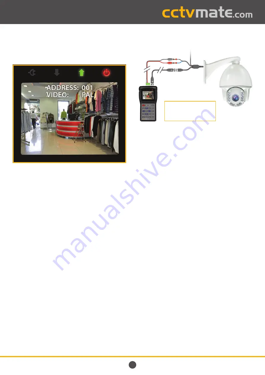
What Information Is Displayed?
As well as the camera’s image, the address (ID) of the PTZ
currently being controlled and video format are also displayed.
If no video signal is received the screen will appear black and
the video will read ‘
NULL
’.
Connecting PTZ Cameras To The LCD330
Connect the PTZ’s video output to the LCD330’s video input
using the BNC to BNC lead provided.
The RS485 test cable supplied is used for connecting the
PTZ’s RS485 contacts to the test monitor. Connect the
‘
Red
’ spring clamp to the PTZ’s ‘
RS485 +
’ contact and the
‘
Black
’ clamp to the ‘
RS485 -
’. On the LCD330 the ‘
RS485 +
’ is
connected to terminal ‘
A
’ and the ‘
RS485 -
’ is connected to
terminal ‘
B
’.
PTZs which use
RS422
are connected in the same way as
those which use RS485.
PTZs which communicate using
RS232
are connected to the
RS232 serial port on the left hand side of the test monitor.
The locations of the LCD330’s connections are highlighted on
page 4
. All of the accessories supplied with the test monitor
are displayed on
page 5
.
Connection Example
RS485 Test
Cable Supplied
+
+
-
-
Video
In
Camera Video
Output
PSU
PTZ
First Things First
Before
you can control or confi gure a PTZ you will need to set
the protocol, communication method and baud rate of the
LCD330 so that they match those of the target PTZ.
The protocol, communication method and baud rate can be
adjusted in the ‘
System Setup
’ menu as explained on
page 7
.
Using The PTZ Test Function
1.
At the main menu press
‘2
’ to enter ‘
VIDEO AND PTZ TEST
’.
2.
To hide the camera’s address and video format press the
‘
MENU
’ button.
3.
The screen brightness can be adjusted using the ‘
BR+
’
and ‘
BR-
’ buttons.
4.
To return to the main menu press and hold the ‘
MENU
’
button for 1 second. The device will beep twice and
display the main menu.
PTZ Address
2.
To change the address to that of the PTZ you wish to
control press the ‘
ADDR
’ button.
3.
‘
NEW ADDRESS
’ will now be displayed on screen. Use the
numeric keypad to enter the address of the desired PTZ.
4.
Press the ‘
OPEN/SET
’ button to confi rm the new address
or ‘
CLOSE/CLEAR
’ to cancel.
The
RS485 +
must be connected
to terminal ‘
A
’ on the LCD330.
The RS485
-
must be connected
to terminal ‘
B
’.
PTZ Testing & Control continues on next page


