background image

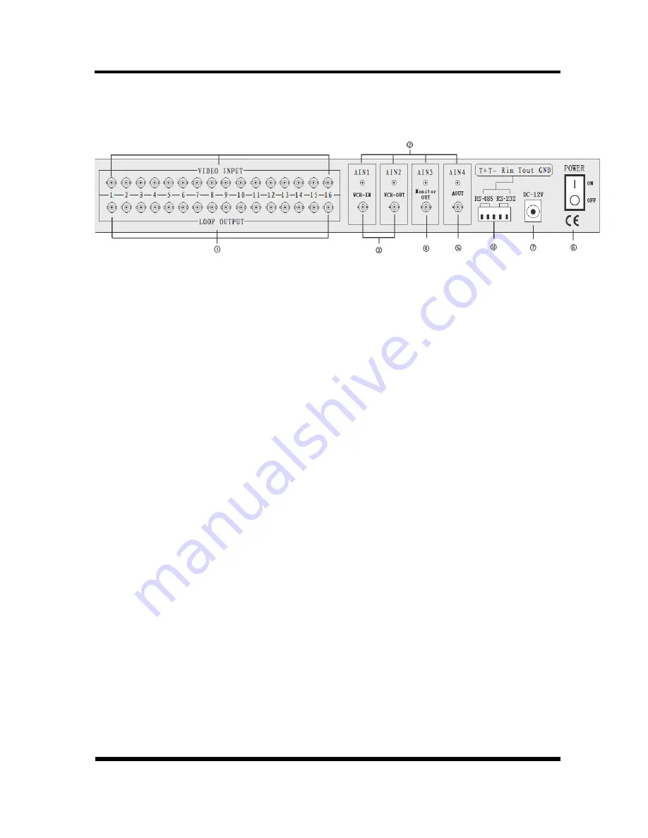
2.Rear Panel Installation

16 Split system


Camera Connection

Accept 16 loop composite video inputs from the camera.

Monitor Connection

Provide 1 composite video output for the main monitor.

VCR OUT Connection

Provide 1 composite video output for recording in the VCR. 

VCR IN Connection

Accept 1 composite video input for playback from the VCR.

AUDIO IN Connection

Accept 4 composite audio inputs from the camera. 

AUDIO OUT Connection

Provide 1 composite audio output for the main monitor.

RS485 / RS-232 Connection

Provide  RS485 interface to control camera.
Provide  RS-232 interface to be controlled by HOST.

Power Switch

           1  

: ON


    ○

 : OFF

Power Jack Connection

          DC 12V/1.5A, Center is positive

3 / 19

Summary of Contents for VM-16RT

Page 1: ...Color 16 Split System User s Manual...

Page 2: ......

Page 3: ...M4 A 6 4 6 Button M4 B 7 4 7 Button M8 7 4 8 Button M9 7 4 9 Button 1 9 FULL 2 10 FULL 3 11 FULL ect 7 4 10 PAL NTSC System 7 4 11 PTZ Function 7 5 Setup Menu Operation 9 5 1 Setup Main menu 10 5 2 Sy...

Page 4: ...n realtime 16 Split Mode Dual Split Mode Auto Sequence Mode High Performance Freeze Function Flicker Free Image Capture High Performance Zoom Function Selectable Zoom Area Various Overlay Information...

Page 5: ...for recording in the VCR VCR IN Connection Accept 1 composite video input for playback from the VCR AUDIO IN Connection Accept 4 composite audio inputs from the camera AUDIO OUT Connection Provide 1 c...

Page 6: ...16 Split picture in picture and Dual Split mode VCR L Enter Playback function ENTER S Enter menu setup M4 A L Enter or Exit PTZ control function M4 A S Master QUAD display up direction button M4 B S...

Page 7: ...4 CH16 8 split and 16 split if turned ON in the Auto sequence setup mode in the display mode windows The time of display video channels can be programmed by menu setup Press any key exit AUTO mode Fre...

Page 8: ...er setup function for select display channel and circle display star area Press up and down key to select item to setup Press left and right key to select which value we needed Press ENTER key again t...

Page 9: ...as full screen 4 10 PAL NTSC System System can be defined as NTSC or PAL standard with the following method The first method is power on with pressing 7 15 or 8 16 key and the second one is to define...

Page 10: ...ing when the ptz controlling is effective The control key definition as follows stop 8 16 FULL automatic pattern right 1 9 FULL left direction 2 10 FULL down 3 11 FULL up 4 12 FULL near 5 13 FULL far...

Page 11: ...up Menu Operation The system provides a built in GUI setup screen For each menu the key function is described in the lower region to help operation The following figure shows the structure of GUI menu...

Page 12: ...p Menu 1 Press to select the item of setup Press to select the value 2 DATA there are three kinds of display format to data MM DD YY DD MM YY YY MM DD Default YY MM DD 07 07 07 3 TIME time setup HH MM...

Page 13: ...to enter into next dialog box Press to select YES and press ENTER to comeback factory setup Default NO Factory Reset Menu WARNING FACTORY RESET EXIT ENTER MENU SELECT THIS SYSTEM GETS TO LOSE THE CURR...

Page 14: ...GRAY1 GRAY2 WHITE OFF 1 DISPLAY ON SCREEN Select YES or NO to display camera title data time in the screen Press to move cursor press ENTER to change state Display 2 SCREEN POSITION Select screen disp...

Page 15: ...RIGHTNESS Brightness setup From 100 to 100 can be selected Press long key value can be continued changed Default 0 4 CONTRAST Contrast setup From 100 to 100 can be changed Press long key value can be...

Page 16: ...AMERA6 01 SEC CAMERA7 01 SEC AUTO SEQUENCE DWELL TIME SELECT EXIT MENU ADJUST PAGE B 8 01 SEC CAMERA10 01 SEC CAMERA12 01 SEC CAMERA16 01 SEC CAMERA9 01 SEC CAMERA13 01 SEC CAMERA11 01 SEC CAMERA14 01...

Page 17: ...er and relay in alarm video loss and motion states Press to select item o and press ENTER to change state is ON Default VIDEO LOSS NO 2 BUZZER HOLD TIME OFF 1ses 99ses can be selected Default 5ses 3 R...

Page 18: ...03 07 07 30 10 LOSS 18 56 03 07 07 30 9 LOSS 17 56 03 07 07 30 6 LOSS 17 56 03 07 07 30 5 EVENT HH MM SS YY MM DD NO 1 OF 6 PAGE SELECT EXIT MENU LIST CLEAR NO SELECT PAGE Display every report of ala...

Page 19: ...WARNING LIST CLEAR EXIT ENTER MENU SELECT THIS SYSTEM GETS TO LOSE THE CURRENT EVENT LIST AND WILL BE INITIALIZED WITH BLINK ARE YOU SURE YES NO 17 19...

Page 20: ...must be connected into together The 5th foot of the serial port connect to the 1th foot of the RS485 RS232 connection 2 The 3th foot of the serial port connect to the 3th foot of the RS485 RS232 conne...

Page 21: ...Unite 0x81 Channel 1 0x96 B Page 8 Unite 0x82 Channel 2 0x97 A Page 9 Unite 0x83 Channel 3 0x98 B Page 9 Unite 0x84 Channel 4 0x99 Non realtime 16 Split 0x85 Channel 5 0x9a 8 A Page 0x86 Channel 6 0x...

Page 22: ......

Reviews: