CCTV SYSTEM
10
Step a.
.
drill a hole on the wall.
⑴
As shown in figure 10, taking the installation holes of bottom
surface of wall bracket as the template, draw the drilling
positions and drill the holes:
Step b. Install bracket and housing:
⑴
Put the video lines, power lines and signal-control lines
through the hollow tube of the wall mounting bracket as the
figure 11 shows.
⑵
Install the speed dome camera on the bracket , and fix it
with 3 PCS screws.
⑶
Fix the installed dome camera to the wall with bulgy
screws.
Note :if the camera is used for outdoor environ-
ment, please seal it to be waterproof.
①
After winding enough PTFE tapes around the
screw thread , screw the housing firmly to the wall
mounting bracket
②
Seal the joint face between wall and the bracket,
holes, and the joint face between bracket and around
the housing with silica gel to be waterproof.
3
、
Wall-hung installation
Step b. fix ceiling mount
There are two connection ways:
One is from center hole, the other is from the hole beside
⑴
Make sure the installation position and the connection way.
Insert the three setscrews in the holes respectively, and then
fasten the screws with gasket and screw cap.(Take the example
of putting the wire through the center of ceiling mount)
Step c. Set speed dome
(1) Set (DIP switches) SW2 under the bottom of dome machine
to control speed dome IP address. (Detailed information can
be found in PART 12
)
(2) Without SW2 DIP switches , setting the IP address by soft-
ware address
refer to Page21
【
Communication settings
】
Step d Line connection
:
⑴
Put video line, power supply line and signal control line
through the round hole in the ceiling mount. ( The type of
wire is shown as figure 9)
Steps e. Dome installation
Insert the three setscrews which are in the bottom of dome
into the holes in the ceiling mount, and then turn the mount as
figure 9 shows to make sure that the screws are inside position-
ing slot firmly.
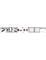
figure
(
10
)
figure
(
11
)
figure
(
8
)
figure
(
9
)
IR Intelligent Speed Dome Operation Manual ver2.0
35
Preset NO.
Speed dome / camera control content
Call preset
Set preset
96
Close the track function
¤
97
Start the tracking scenario 1 the corresponding preset 88
¤
98
Start the tracking scenario 2 the corresponding preset 89
¤
99
Start the tracking scenario 2 the corresponding preset 90
¤
100
Start the tracking scenario 4 Corresponding to the first set
of 1-16 presets a cruise
¤
97
Set the low sensitivity
¤
98
Set the middle of sensitivity
¤
99
Set the high sensitivity
¤
100
Tracking lens time close
¤
101
Tracking lens time open
¤
4.Auto-Tracking Function Express
101
The user can arbitrarily set the distance light according to
the camera multiple switching mode 1
¤
102
The user can arbitrarily set the distance light according to
the camera multiple switching mode 2
¤
103
IR cut open
¤
103
IR cut close
¤
133
IR light near brightness with the lens set multiple relation-
ship
¤
134
IR light brightness with the lens set multiple relationship
¤
135
IR light far brightness with lens multiple relationship
¤
136
The maximum brightness settings for all lamp: [set No.
136 set 50-100 preset, (where 50-100 corre-
sponds to the maximum brightness brightness 50%-100%)]
¤
137
An infrared detection threshold setting: [No. 137 set
36-100 preset, (where 36-100 corresponding infrared sensi-
tivity values lower easily switch to the infrared mode])
¤
128
Set fan start temperature: (set No. 128 set 1-
80preset, 1-80 corresponds to 1-80 degrees)
¤
129
Close the lamp with the fan linkage function
¤
129
IR light with fan linkage function to open the lamp and
fan synchronous open
¤
5.IR Function Express