CCTV EX-17LBE User Manual Download Page 7

Standards and Guidelines 

3.1 

FCC Requirements 


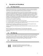
This device complies with Part 15 of the FCC Rules and Regulations. Operation is subject to the following 
two conditions: (1) This device may not cause harmful interference, and (2) this device must tolerate any 
interference encountered, including interference that may cause improper operation. 

The equipment has been tested and found to comply with the requirements stipulated in Part 15 of FCC 
regulations for a Class B digital device. These requirements are designed to provide reasonable protection 
against harmful interference in a residential installation. This equipment generates, uses and can radiate 
radio frequency energy and, if not installed and used in strict compliance with the instructions, may disrupt 
radio communications. However, there is no guarantee that interference will not occur in a particular 
installation. If this equipment does cause detrimental interference with radio or television reception, which can 
be determined by turning the equipment off and on, the user is encouraged to try to correct the interference 
by taking one or more of the following measures: 


Reorienting or relocating the receiving antenna. 


Increasing the separation between the equipment and the receiver. 


Connecting the equipment into an outlet on a circuit different from the one which the receiver is connected. 


Consulting the dealer or an experienced radio/TV technician for help. 

Shielded interconnected cables and shielded power cords must be used with this equipment to ensure 
compliance with the pertinent RFD emission limits governing this device. 

Changes or modifications not expressly approved by the manufacturer could void the user’s right to operate 
the equipment. 

Notice of Compliance with Canadian Interference-causing Equipment Regulations 

This Class B digital apparatus meets all requirements of the Canadian Interference-Causing Equipment 
Regulations. 

3.2 

FCC Warning 


To ensure continued FCC compliance, the user must use a grounded power supply cord and the shielded 
video interface cord with bonded ferrite cores provided. If a BNC cable is going to be used, use only a 
shielded BNC (5) cable. Also, any unauthorized changes or modifications not expressly approved by the 
party responsible for compliance could void the user’s authority to operate this device. 

3.3 

CE Conformity  


The device complies with the requirements of the directive 
2004/108/EC   with regard to “Electromagnetic compatibility”, and 
206/95/EC with regard to “Safety”. 


                                                                                                                        5 


E

n

g

lis

h


F

ra

n

ç

a

is


D

e

u

ts

c

h


E

s

p

a

ñ

o

It

a

lia

n

o


P

o

ls

k

Č

e

s

k

y


S

v

e

n

s

k

a


N

e

d

e

rl

a

n

d

s


Summary of Contents for EX-17LBE

Page 1: ...CCTV LCD Monitor User Manual For models EX 17LBE EX 19LBE _____________________...

Page 2: ...e United Kingdom 4 3 Standards and Guidelines 5 3 1 FCC Requirements 5 3 2 FCC Warning 5 3 3 CE Conformity 5 3 4 RoHS Compliance Statement 6 3 5 Information on Disposal for Your Old Product 6 4 Hardwa...

Page 3: ...he user manual is applicable to your machine 1 The LCD monitor is used in the same way as the CRT monitor There is no need to change the hardware of your computer just plug it in and it is ready for u...

Page 4: ...ained to ensure reliable and continued operation and to protect the LCD monitor from overheating Do not block ventilation slots and openings with objects or install the LCD monitor in a place where ve...

Page 5: ...rements and may look like this Figure A1 below Figure A1 Figure A2 2 3 1 For the United States and Canada In the United States and Canada the male plug is a NEMA5 15 style Figure A2 above UL Listed an...

Page 6: ...een and Yellow Ground Earth Blue Neutral Brown Live If the colored wires of the mains lead of this appliance do not correspond with the colored markings identifying the terminals in your plug proceed...

Page 7: ...ncreasing the separation between the equipment and the receiver Connecting the equipment into an outlet on a circuit different from the one which the receiver is connected Consulting the dealer or an...

Page 8: ...ing of used electrical and electronic equipment When this corssed out wheeled bin symbol is attached to a product it means the product is covered by the European Directive 2002 979 EC If you wish to d...

Page 9: ...rrect installation procedures for the LCD monitor 4 1 Checking the Accessories Supplied LCD monitor body Desk Stand x 1 pc AC power cord x 1 pc Adaptor x 1 pc D Sub 15 pin cable 1 8 Meter x 1 pc 3 5mm...

Page 10: ...also Enter the OSD menu 3 Power Press button to turn the power on and press again to turn the power off Up Increase To move the cursor upwards or to switch over the setting items or to increase the fi...

Page 11: ...e output connector EX 19LBE Item Connector Function 1 PC Audio Input 3 5mm Connect to the audio output of your computer 2 DC 12 Input Please use DC 12V 5A Power Adaptor 3 D Sub VGA Input Connect to th...

Page 12: ...s Brightness Press or V to increase decrease the bar to adjust brightness Adjusting brightness to enhance the level of dark area in the video picture such as night scenes and shadow scenes Increasing...

Page 13: ...l out the OSD Menu Press or V to select Misc mode and press A key again to select the Misc option Signal Source Press or V key to select signal source Reset If you want to back to factory default pres...

Page 14: ...Setting option Clock Use Clock to fine tune the monitor when phase value is wrong Press or V to increase decrease the bar to adjust the Clock Phase Use phase to fine tune the monitor to perfectly ADC...

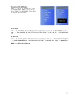
Page 15: ...e picture You may press or V key to select H Position and press key to increase bar to shift the picture to right or press V to decrease bar to shift the picture to left V Position Use to change verti...

Page 16: ...the front of LCD Monitor is in still green Check if the computer or AV equipment video signal cables are properly secured Abnormal image Check and make sure the computer or AV equipment video signal...

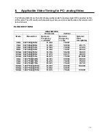
Page 17: ...Hz Nominal Frequency 1 Hz Nominal Pixel Clock MHz VGA 640 350 70Hz 31 469 70 087 VGA 640 480 60Hz 31 469 59 940 25 175 VGA 640 480 75Hz 37 500 75 000 31 500 DOS 720 400 70Hz 31 469 70 087 28 322 SVGA...

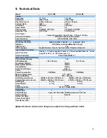
Page 18: ...h Italian Russian Chinese 7 Input Output Connector Input Connector D Sub x 1 PC Audio Input 3 5 Jack x 1 Video Input BNC Jack x 2 Power Input DC 12V 5A x 1 RCA Video input x 1 Output Connector Video O...

Page 19: ...10 Dimension EX 17LBE EX 19LBE 17...

Reviews: