Overview
11
When connecting the WattNode, do not place more than one voltage wire in a screw terminal; use separate
wire nuts or terminal blocks if needed. The screw terminals handle wire up to 12 AWG. Prepare the
voltage wires by stripping the wires to expose 1/4" (6 mm) of bare wire. Do not leave more than 5/16" (8
mm) or less than 3/16" (5 mm) of bare wire. Connect each voltage line to the light gray terminal block as
shown in the section
Measurement Configurations
. Double check that the voltage line phases match
the phases to which the CTs are connected. After the voltage lines have been connected, make sure both
terminal blocks are securely installed on the WattNode.
If there is any doubt that the voltage rating of the WattNode is correct for the circuit being measured, then
before applying power to the WattNode, disconnect the light gray screw terminal from the WattNode and
then turn on the power. Use a voltmeter to measure the voltage between the top two screw terminals—
labeled NEUTRAL and øA on 1P and 3Y models, and labeled øA and øB on 3D models. This voltage
should match the value in the VAC column of
Table 2: Power and Energy Parameters
.
The WattNode is powered from the voltage inputs: phase A to neutral, or phase A to phase B for delta
models. If the WattNode is not receiving at least 80% of the nominal line voltage, it may stop measuring
power. Since the WattNode consumes some power itself, a decision must be made about whether to place
the CTs before or after the connection for the WattNode, so as to include or exclude the WattNode’s own
power consumption (up to 3 watts).
Connecting Output
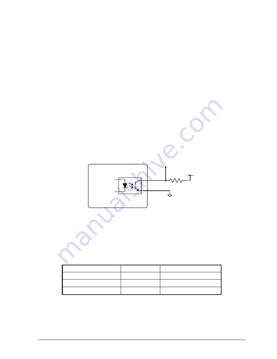
The outputs of the WattNode are the collector and emitter of an NPN optoisolator transistor whose base is
driven by the WattNode’s pulse stream. This output may be connected to most devices that expect a
contact closure input. The following schematic illustrates a possible connection to the optoisolator.
0-5V output
+5V
R
c
WattNode
+
–
Figure 6: Optoisolator Output
Under no circumstances, should the optoisolator ever be exposed to collector-emitter voltages greater than
35V, or collector-emitter currents greater than 50mA.
The value chosen for R
c
depends on the maximum pulse frequency expected from the WattNode. If power
consumption is of no concern, then a value around 1K
Ω
will work for all output frequencies and provide
short rise and fall times. For cases where power consumption is a concern and slow rise and fall times may
be tolerated, then the following table shows the maximum value of R
c
for various maximum pulse
frequencies.
Maximum Frequency
Maximum R
c
Risetime to 4.0V
4.0 Hz
2.2 M
Ω
70 milliseconds
290 Hz
82 k
Ω
1.6 milliseconds
1200 Hz
4.7 k
Ω
100 microseconds
Table 1: Collector Resistors vs. Frequency


