INSTALLATION MANUAL
V1.3EN
BLEU
TITANE
RT
I
-EZ
CCEI
p
5
INSTALLATION
The heater can be connected directly to pipes with diameter 50 mm or 63 mm.
To use our equipment in the best conditions, we recommend observing the following
parameters in the case of a water treatment with chlorine:
• pH between 6.9 and 7.5.
• Chlorine free active between 0.4 and 1.4 mg / l.
In the case of other type of water treatment, the installer has to check compatibility
with our equipment.
Hydraulic connection
The heater must be installed before any water treatment device. It is strongly
recommended to keep the pipelines of the heater filled with water. After
stopping the pump, the heater must not be emptied by gravity.
The heater can be inserted into a pipe of diameter 63 mm or 50 mm. In 50mm case,
the two adaptor provided must be affixed to both ends of the heater. No additional
piece of PVC is required.
All heaters are supplied with a flow switch. From factory, the heater is configured to
operate with water moving from left to right. (See diagram below).
It is possible to reverse the direction of flow of water by turning the flow switch:
- Switch the filtration pump off and ensure that the heater is not under pressure.
- Unscrew the flow switch. Turn the flow switch 180 degrees. (Do not remove
the gasket that is under the cap). Screw the flow switch.
- Switch on the filtration pump to check that there is no leakage.
- Close the heater and check that the heater stops immediately when the filter
pump is off.
Electrical connection
The heater must be powered from a line protected by a 30 mA differential device
(GFCI). The power supply cable must have a section adapted to the power of the
heater. The appliance must be correctly grounded.
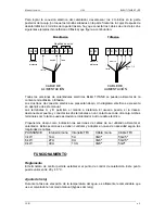
To achieve the electrical connection of the heater, unscrew the 4 screws at the back
of the box (do not touch the screws are on the front of the box). After unscrewing the
4 screws from the rear, you must connect the wires according to one of two examples
given below (single or three phase).
Replace the housing by screwing the four screws from the back of the box.
The table below shows cable section to be used according to the power of the
heater. The cable section must adjusted according to the length of cables.
Flow direction


