background image


Confidential 

  21  / 73 

2020/06/28 


2.2.3


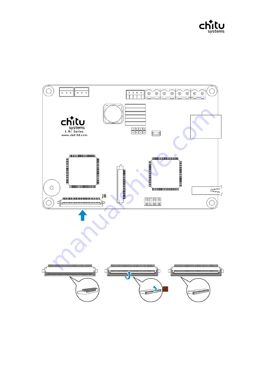
Installing the LCD panel (printing screen) 

As shown following steps, connect the LCD panel cable(printing screen), as shown 

J6

on the 

board. 

①、

Find the LCD panel connector 

As shown below, the 

J6

  on the controller board. 


②、

Open the cover of the connector 


As shown below, put your thumbs on the cover and open it lightly. 


Summary of Contents for ChiTu L M1

Page 1: ...ChiTu L M1 Manual CBD Tech Controller Board ...

Page 2: ...this manual or any information obtained through this manual The user shall bear all risks of using this manual The user clearly understands and agrees that neither CBD Tech CBD Tech s authorized person and its directors employees agents or related companies need to be responsible for this manual for the use of this manual or for any blame Derivation incidental direct indirect special punishment or...

Page 3: ...ctual property rights of the third party product names or contents mentioned in this manual are owned by the respective product or content owners and are protected by the current intellectual property related laws and international treaties When the following two situations occur this product will no longer be subject to CBD Tech s warranty and service 1 This product has been repaired changed spec...

Page 4: ...LED 10 1 1 Controller board overview 11 1 2 Controller board Layout 12 1 3 Component overview 13 Installation Flow 16 2 1 Installation overview 16 2 2 Regular installation 17 2 4 Firmware update 28 User guide 33 3 1 Function list 33 3 2 Icon overview 34 3 3 Page structure 35 3 4 Page description 36 3 5 Function guider 44 Others 73 4 1 Contact Us After sale 73 ...

Page 5: ...staff If the power supply is damaged do not try to repair it by yourself Please refer it to professional technical service personnel Operational safety Before you install the controller board and add hardware devices be sure to read the relevant information provided in this manual in detail Before using the product make sure that all cables and power cords are properly connected If you find any ma...

Page 6: ...oard In addition the use timing and parameter setting of each setting value of the firmware program will be introduced in detail Chapter 3 After sales support This chapter mainly introduces the official channels for product after sales and technical support Conventions used in this guide In order to ensure that you complete the controller board settings correctly please pay attention to the specia...

Page 7: ...t all kinds of information about ChiTu Systems products 2 Other documents In addition to the standard accessories listed in this manual other documents may be included in your product packaging box such as the product warranty document attached by the dealer Caution This product enjoys a one year product warranty period If you tear or replace the original factory warranty serial number label you w...

Page 8: ...he accessories listed above are damaged or missing contact your dealer as soon as possible The above illustrations are for reference only the actual product specifications may vary depending on the model Item Description Controller Board ChiTu L M1 Series Touch Screen 2 8 3 5 4 3 5 0 7 0 inch FFC Cable 0 5 40 FFC Others User manual Connector ...

Page 9: ...icroprocessor Chip ARM STM32F4 Series Stepper Motor Chip Trinamic TMC2209 Flash Memory Chip 64M EtronTech EM Series eMMC 4GB eMMC 5 1 Voltage Current 12 24V 5 12A Environmental parameters LCD Resin Panel 1 port type MIPI USB 1 port USB 2 0 Type A Ethernet 1 port Others Recommended format CHITUBOX Supported format ctb Firmware version Subject to actual batch Basic Information Parameter Information ...

Page 10: ...ontroller board S N Serial Number sticker or warranty sticker provided by your dealer These stickers are required for warranty validation Always remove the AC power by unplugging the power cord from the power outlet before installing or removing the controller board or other hardware components When connecting hardware components to the internal connectors on the controller board make sure they ar...

Page 11: ...er LED that lights up to indicate that the system is ON in sleep mode or in soft off mode This is a reminder that you should shut down the system and unplug the power cable before removing or plugging in any controller board component The illustration below shows the location of the onboard LED ...

Page 12: ...Confidential 11 73 2020 06 28 1 1 Controller board overview 1 1 1 Screw holes Place 4 screws into the holes indicated by circles to secure the controller board to the chassis ...

Page 13: ...5 Mainboard fan port 3 ARM STM32F4 series CPU 16 UV LED fan port 4 USB 2 0 port 17 UV LED port 5 External motor driver pin 18 Power supply 6 Z motor driver pin 7 TFT resistive touch screen 8 ANOLOGIC EL2F series FPGA chip 9 LCD resin panel 10 Buzzer 11 Z endstop minimum position 12 Z endstop maximum position 13 Z motor ...

Page 14: ...nected 1 3 3 UV LED fan This port is for control and signals the LED light fan device connected 1 3 4 Mainboard fan This port is for control and signals the mainboard fan connected 1 3 5 Z stepper motor This port is for control and signals the Z axis stepper motor connected Pin Name Pin Tag Number Definition Description 1 1B Coil 1 end B 2 1A Coil 1 end A 3 2A Coil 2 end A 4 2B Coil 2 end B Z Moto...

Page 15: ... This port is for control and signals the external Z axis stepper motor connected Pin Name Pin Tag Number Definition Description 1 VCC Power Output 2 GND GND 3 S Signal pin Z Endstop Maximum position Z Pin Name Pin Tag Number Definition Description 1 VCC Power Output 2 GND GND 3 S Signal pin Z Endstop Minimum position Z Pin Name Pin Tag Number Definition Description 1 DIR Direction 2 EN Enable 3 S...

Page 16: ...en port connected 1 3 12 USB 2 0 This port is for read the USB 2 0 connected 1 3 13 Buzzer This component will emit a beep sound to remind you of the completion of an operation or an abnormal error 1 3 14 Ethernet port This port is for Ethernet connected LED picture LED name Status Description Blinking High Frequence Data activity Yellow Sleep mode Green Connection succeeded Off Connection failed ...

Page 17: ...Confidential 16 73 2020 06 28 Installation Flow 2 1 Installation overview ...

Page 18: ...idential 17 73 2020 06 28 2 2 Regular installation 2 2 1 Installing power supply As shown below connect the power supply wire with 12V 24V port As shown below the arrow shows the where 12V 24V on the board ...

Page 19: ...wn following steps connect the touch screen cable FFC cable Find the screen connector on the board As shown below U13 on the board Pull out the black bar As shown on put your finger on each side of the black bar mark as red pull out the bar to follow the arrow direction as shown on ...

Page 20: ...rds up stiffeners shielded side usually the blue side towards down make sure to insert the cable all the way till it can t move forward anymore Close the black bar back As shown on put your finger on each side of the black bar mark as red push back the bar to follow the arrow direction as shown on ...

Page 21: ...73 2020 06 28 Connect the touch screen Use the same way to connect the rest side of FFC cable with touch screen on the contrary stiffeners shielded side towards up and pin side toward down as usual Installing finished ...

Page 22: ...screen As shown following steps connect the LCD panel cable printing screen as shown J6 on the board Find the LCD panel connector As shown below the J6 on the controller board Open the cover of the connector As shown below put your thumbs on the cover and open it lightly ...

Page 23: ...the stiffeners shielded side usually dark brown color towards up pin side towards the board make sure to insert the cable all the way till it can t move forward anymore Close the cover of the connector As shown below press the cover slowly to close the connector ...

Page 24: ...Installing UV LED light Insert the 2 pins of the UV LED light into LED on the controller board you can also install different light source as your demand COB Reflective Cup Parallel LED array As shown below the LED on the controller board ...

Page 25: ...Confidential 24 73 2020 06 28 2 2 5 Installing UV LED fan Insert the 2 pins of the UV LED light fan into LED_F on the controller board As shown below the LED_F on the controller board ...

Page 26: ...Confidential 25 73 2020 06 28 2 2 6 Installing controller board fan Insert the 2 pins of the controller board fan into MB_F on the controller board As shown below MB_F on the controller board ...

Page 27: ...Confidential 26 73 2020 06 28 2 2 7 Installing Z stepper motor Insert the 4 pins of the z stepper motor into Z_MOTOR on the controller board As shown below the Z_MOTOR on the controller board ...

Page 28: ...Confidential 27 73 2020 06 28 2 2 8 Installing Z axis minimum end stop Insert the 3 pins of the Z axis minimum end stop into Z on the controller board As shown below Z on the controller board ...

Page 29: ...ww cbd 3d com to get the firmware version corresponding to the controller board and download 文件名 描述 xxxxx cbd FPGA File xxxxx gcode Parameter file xxxxx logo Startup page UI_xxxxx bin UI file update lcd Update file 用途 FPGA core function file Part of the control parameter file of the printer The startup page after the printer is turned on User interface of firmware program The core function file of...

Page 30: ...Check the current firmware version Open the 3d printer click the system of the main page you will enter the system page In the system page click the Information you will enter Information page In the Information page the info after is the current firmware version ...

Page 31: ...pty or has been formatted In order to ensure update process without any issue please ensure that the U disk The remaining space is above 1G and all files should be placed in the ROOT directory of the U disk E Insert U disk Power off the printer Insert the U disk into your printer or the USB interface of the board F Update core firmware file Turn on the printer and it will automatically retrieve th...

Page 32: ... 31 73 2020 06 28 G Update other files Click Print you will enter file list page In this page you can see all the files and folders in the U disk choose the firmware you want to update you will enter file info page ...

Page 33: ...er will read the file and start upgrade automatically During the updating please DO NOT click any button in case of updating failed There will emit twice a beep sound to remind you of the completion of firmware updating Restart the printer to check Same way for all the firmware format update ...

Page 34: ...es Description Page U disk read 43 44 File list display 43 44 File deleted 46 47 File preview 45 Local printing 48 49 Network printing 52 54 Parameter setting 55 57 Pause printing 50 Resume printing 50 Stop printing 51 Clean 58 59 Z control 64 65 Z reset 62 63 Exposure test 60 61 Language Switch 66 67 Beep on off 68 69 Systems info 70 After sale info 71 File management Printing control Component c...

Page 35: ...ll move one unit down close to the resin tank Click it and the platform will move to the default height Enter to the settings page In the file list page click to view the list file on the previous page In the parameter settings page click to increase the parameter value by one unit In the file list page click to view the list file on the next page In the parameter settings page click to decrease t...

Page 36: ...Confidential 35 73 2020 06 28 3 3 Page structure ...

Page 37: ...l enter Tool page System enter System page Print enter Print page 3 4 2 Tool page Include exposure test component calibration etc Manual Enter Move Z axis page Exposure Enter Exposure testing page Set Z 0 pop up window for Z to zero Stop to stop all current commands and mechanical movements Clean enter Resin vat clean page ...

Page 38: ...of stepping travel Reset the platform to default height you set Move Z up Z axis will move up the current value unit you choose Move Z down Z axis will move down the current value unit you choose Stop click to stop the Z moving 3 4 4 Exposure page Tag Exposure image exposure image in test state Tag Status info remind user the printer is current in the exposure test status ...

Page 39: ... is 200s click to enter parameter input page Tag increase exposure time add one second every click Tag decrease exposure time cut one second every click Tag Next button click will save the current setting and enter exposure page 3 4 6 Clean page Tag Clean image exposure image in vat clean state Tag Status info remind user the printer is current in the vat clean exposure status ...

Page 40: ...he file is read from the U disk This icon means the file is read from the local storage Tag Last page click to flash the current list and show the previous first four files or folders Tag Next page click to flash the current list and show the first four files or folders 3 4 8 File info page Display the detailed information of the file you can delete print the file in this page Tag File name and fi...

Page 41: ...inted Tag Print time remaining the time needed to finish printing it is better to check after bottom layers finished Tag Printed time the time from you start printing Tag The number of slicing layers former are layers has printed the latter is total layers volume Tag Stop printing click to stop the printing Tag pause resume printing click the button will pause the current print Click the button wi...

Page 42: ... the exposure time during the printing click to enter parameter input page Light off delay The Light off delay is the time during LED light off from the last layer to the next layer this setting is for extra preparing time before the next layer start exposure click to enter parameter input page 3 4 11 Parameter input page Adjust and save the current parameter setting Tag Current parameter Tag Keyb...

Page 43: ...ck to enter Network page Service click to enter Service page Language click to language page Calibration click to calibration page 3 4 13 Information page Display the key information of board Tag The series and model number of this controller board Tag The serial number of this board Tag The firmware name and version of this board Tag Beep on off means beep on status means beep off status ...

Page 44: ...Confidential 43 73 2020 06 28 3 4 14 Service page The official after sale and tech support information ...

Page 45: ...ad U disk A Insert U disk Insert the U disk include printing file into the printer B Click Print Click the Print button on the main page enter file list page C Check U disk file list On this page you can view the list of files and folders in the current U disk ...

Page 46: ...Confidential 45 73 2020 06 28 When you have not inserted a USB flash drive this page displays a blank list ...

Page 47: ...Print Click the Print button on the main page enter file list page B Choose model file Choose one of the models with the file format can be previewed enter file info page Note the file can t be previewed if the format not support preview C Enter File info page ...

Page 48: ... 28 3 5 3 Delete file A Click Print Click the Print button on the main page enter file list page B Choose model file In this page you can choose the file you want to delete C Choose model file Choose the file you want to delete ...

Page 49: ...2020 06 28 D Click delete button In this page you can click the in the right side there will be a box to confirm if delete or not E Click Confirm Click Confirm the file will be deleted Click Cancel the box will be closed ...

Page 50: ... 4 Local printing method Flow of local printing Detailed steps for local printing A Click Print Click the Print button on the main page enter file list page B Enter File list page In this page you can choose the file you want to print ...

Page 51: ...al 50 73 2020 06 28 C Choose a model file Choose a model file you want to print D Enter File info page In this page you can preview the 3D file E Click Print button Click the in the right side then start printing ...

Page 52: ...nting In Printing process page click the button in the right side printing will pause and Z axis will move up to default setting height B Resume printing In Printing process page click the button in the right side printing will start again from the last layer to finish the print file ...

Page 53: ...0 06 28 C Stop printing In Printing process page click the button in the right side there will be a box to confirm if stop or not Click Cancel the printing will continue Click Confirm the printing will stop and exit the page ...

Page 54: ...73 2020 06 28 3 5 6 Network printing Flow of network printing Detailed steps for network printing A Open CHITUBOX software Open the CHITUBOX in your PC or laptop B Import STL file Open file or drag the file to CHITUBOX ...

Page 55: ...0 06 28 C Settings Click Settings make sure use the default mode D Click Slice After settings click Slice and wait the slicing process to complete E Click Network sending After slicing click Network sending in the right side ...

Page 56: ...Confidential 55 73 2020 06 28 F Send file In Network sending box click Printer name list select the printer or board that connected to the LAN click the file will send to the printer ...

Page 57: ... of printing setting Detailed steps for printing setting A Printing process page The printing setting can only edit when the file is printing B Click Printing setting button In printing process page click the button in the right side to enter printing setting ...

Page 58: ...Printing setting page For now you can edit 4 parameters bottom layer count bottom exposure time exposure time and light off delay D Choose the parameter to set Click the parameter enter the Parameter input page E Enter Parameter input page ...

Page 59: ...Confidential 58 73 2020 06 28 F Keyboard input area Input the number value on keyboard input area G Click Save button After input click button in the right side to save ...

Page 60: ...28 3 5 8 Resin tank clean Flow of resin tank cleaning Detailed steps for resin tank cleaning A Click Tool button Click the Tool button on the main page B Click Clean button Click Tool button enter Clean exposure time setting page ...

Page 61: ... time parameter In this page you can adjust the time by or button or click Parameter input page to input by manual D Click Next After input the parameter click Next to enter Exposure process page E Enter Clean process page Wait the process finish ...

Page 62: ... 73 2020 06 28 3 5 9 Exposure test Flow of exposure testing Detailed steps for exposure testing A Click Tool button Click the Tool button on the main page B Click Exposure Click Exposure button enter the Exposure page ...

Page 63: ... time parameter In this page you can adjust the time by or button or click Parameter input page to input by manual D Click Next After input the parameter click Next to enter Exposure process page E Enter Clean process page Wait the process finish ...

Page 64: ...Confidential 63 73 2020 06 28 3 5 10 Z platform reset A Click Tool button Click the Tool button on the main page B Enter Tool page C Click Manual button Click Manual button to enter the Manual page ...

Page 65: ...Confidential 64 73 2020 06 28 D Click Home button Click button the Z platform will automatically move to the default height ...

Page 66: ...3 5 11 Control the Z platform Flow of controlling the Z platform Detailed steps for controlling the Z platform A Click Tool button Click the Tool button on the main page B Click Manual button Click Manual button to enter Manual page ...

Page 67: ...fidential 66 73 2020 06 28 C Enter Manual page D Set stepper value Set the stepper value for up or down E Click Up or Down button Click or button Z axis will move Up down the current value unit you choose ...

Page 68: ...Confidential 67 73 2020 06 28 3 5 12 Language Switch Flow of language switching Detailed steps for language switching A Click System button Click System button in the main page B Enter System page ...

Page 69: ...Confidential 68 73 2020 06 28 C Click Language button Click Language button there will be a Language switched box D Click Confirm button ...

Page 70: ...al 69 73 2020 06 28 3 5 13 Beep on off Flow of turning on off the beep Detailed steps for turning on off the beep A Click System button Click System button on the main page B Enter System page C Click Info button ...

Page 71: ...0 73 2020 06 28 D Enter Info page E Click Beep button means beep on status click to switch to The system will enter the sound off mode means beep off status click to switch to The system will enter the sound on mode ...

Page 72: ...ormation A Click System button Click System button on the main page B Click Info button Click Info button on the System page C Enter Info page This page you can the key information of board The series and model number of this controller board ...

Page 73: ...Confidential 72 73 2020 06 28 3 5 15 Service A Click System button B Click Service button Enter System page click Service button C Enter Service page The official after sale and tech support information ...

Page 74: ...n District Shenzhen Channel CBD Tech Link address https www facebook com CBD3D QR code Official Facebook Channel ChiTu Systems Link address https www facebook com groups 524123865039248 QR code Official Facebook Group Channel ChiTu Systems Link address https twitter com chitusystems QR code Official Twitter Channel chitu_board Link address https www instagram com chitu_boar d QR code Official Inst...

Reviews: