background image


20

Mounting 

VESA Bracket 


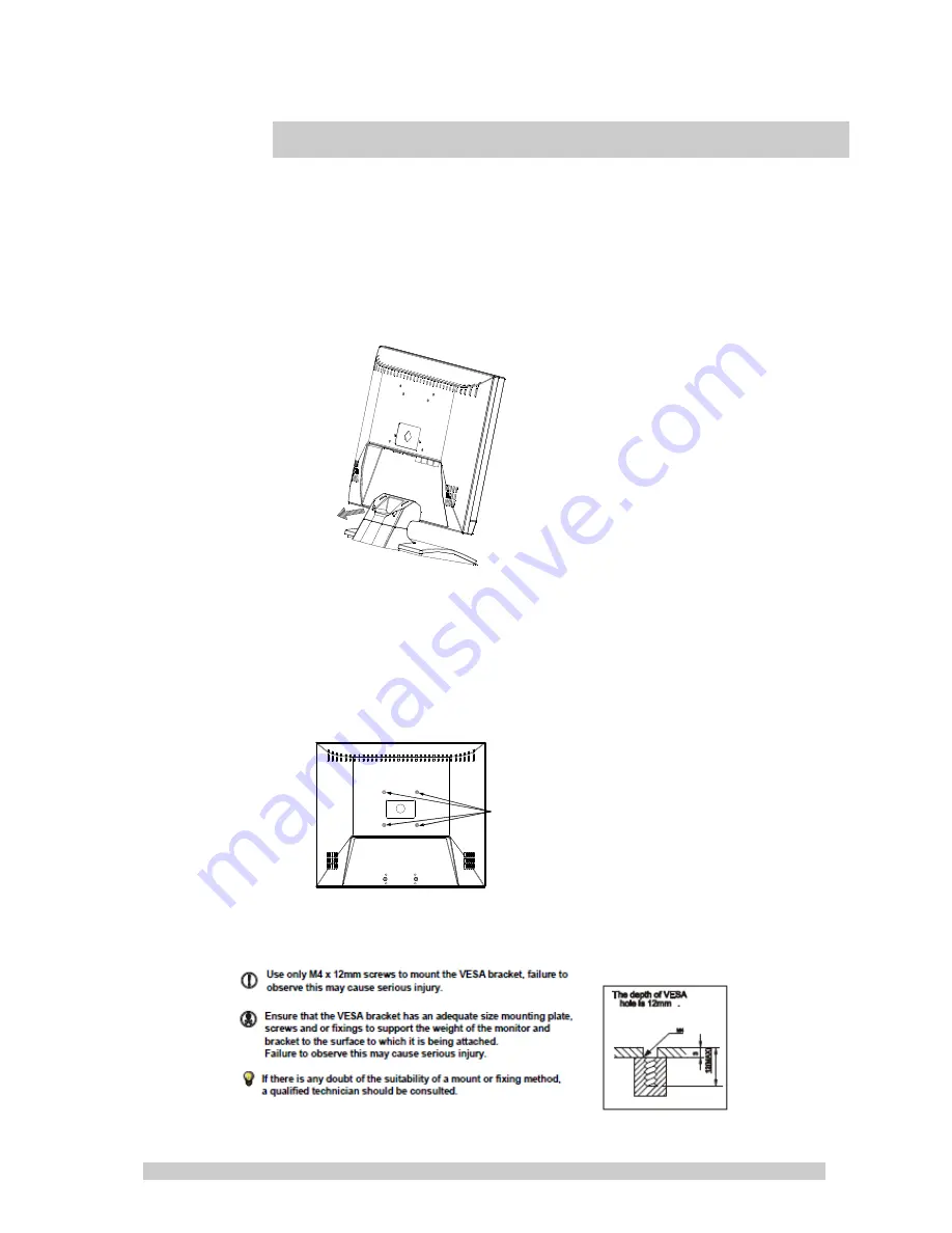
Lay the LED display face down on a towel or blanket.   Note the 
4 screws that secure the hinge on the lower part of the back 
casing. These may be removed to release the desk mount 
bracket if required. 


Attach a VESA compatible mounting bracket  

(VESA 75mm x 75mm  is supported) 


4 screw for VESA 75mm


Summary of Contents for LME17

Page 1: ... missing please contact with your local distributor Please save the packing box for possible future return for service Package Contents One LED Monitor 12V DC Adapter Power cord D Sub 15 pin VGA connector Cable User s Guide Hardware Installation The following sections in this guide give clear step by step descriptions of the installation process and explain how to use the monitor for optimum resul...

Page 2: ...uages English German French Italian Spanish Russian Turkish Japanese Polish Auto Adjustment Yes De interlace Yes Wall mount Yes Optional 75mm VESA mount Accessories Manual Power Adaptor VGA cable Safety FCC CE ROHS Tilt 5 15 C Humidity 10 90 Monitor scan Microprocessor controlled Horizontal frequency 31kHz 65kHz 56Hz 75Hz DPMS DDC1 2B Vertical frequency VESA specifications Pixel pitch 0 264x0 264m...

Page 3: ...0 37 879 60 317 8 800x600 72 48 077 72 188 9 800x600 75 46 875 75 000 10 1024x768 60 48 363 60 004 11 1024x768 70 56 476 70 069 12 1024x768 75 60 023 75 029 13 1280x1024 60 63 981 60 020 14 1280x1024 75 79 976 75 025 Note 1 Please note selecting frequencies outside these ranges may result in an abnormal images or damage to the monitor 2 The resolution will be showed on the screen while VGA mode be...

Page 4: ...t Composite Video Input HDMI Input On screen Display OSD with Multiple Languages PIP POP Function Quick Installation 1 Connect power cord and power adaptor 2 Connect video cable Make sure both the LED display and computer are turned off Connect the video cable from the LED display to the computer 3 Turn ON LED display and computer 4 Select input source Select the proper input source corresponding ...

Page 5: ...tor will be display Automatically adjusts H Position V Position Pixel Clock and Phase for an optimal image in PC mode only Switch setting item Increase the value of the choose item Switch setting item Decrease the value of the choose item Select Source PC AV1 AV2 while in the OSD menu this button is used as select advance and confirm Enter the main menu of the on screen display OSD Source Select P...

Page 6: ...econds Please press the power button again to restart the monitor LED Status Display The following table describes the various power states of the LED monitor as represented by different LED colors Note The LED will also be red if AV1 or AV2 is selected and there is no video signal detected Power State LED Color On Green Standby Red No power Blank ...

Page 7: ... Setup Setup for multiple signal display Press the keys to select the appropriate function then press the select button to access and to advance within that menu Use the keys to change the parameter then press select button to confirm and advance to the next selection When the setting completed press the menu button to return to the main menu Press the menu button again to exit OSD programming 3 O...

Page 8: ...image contrast Press OR to adjust the parameter 4 Tint This is used to adjust the image Tint Press OR to adjust the parameter 5 Saturation This is used to adjust the image saturation Press OR to adjust the parameter 6 Sharpness Adjust the sharpness It makes the image become soft Press OR to adjust the parameter 7 Color Temp Press OR to adjust the color tones Cool Warm Normal 8 DNR Press OR to adju...

Page 9: ...9 Sound Mode 1 Volume Press OR to adjust volume level 2 Mute Press OR to select sound Off On ...

Page 10: ...cture Press OR to adjust the parameter 4 V Position Move the display picture up or down Press OR to adjust the parameter 5 V Zoom Adjust the V size of the display picture Press OR to adjust the parameter 6 Scale Mode Adjust the V size of the display picture Press OR to adjust Full 16 9 7 Reset Recall Default value PIP POP Setup Mode 1 Multi Window Press OR to select PIP POP Off mode ...

Page 11: ...o select U L B L B R U R position 5 Border Color Choose the border color of Sub Source window Press OR to select Black Blue color 6 Sound Source Press OR to select Main Sub mode 7 Swap Press Select to Swap the Source of Main and Sub Note AV1 and AV2 can not be displayed at the same time on the monitor in PIP POP mode If POP mode is selected both images are scaled to fit the screen ...

Page 12: ...he screen Press OR to adjust the parameter 2 Brightness This is used to adjust the image contrast Press OR to adjust the parameter 3 Color Temp Press OR to adjust the color tones Cool Warm Normal 4 Auto Adjust Select Auto Adjust to Auto synchronizes screen to graphics adaptor ...

Page 13: ...13 Sound Mode 1 Volume Press OR to adjust volume level 2 Mute Press OR to select sound Off On ...

Page 14: ...Press OR to adjust the parameter 4 V Position Move the display picture up or down Press OR to adjust the parameter 5 V Zoom Adjust the V size of the display picture Press OR to adjust the parameter 6 Clock Press OR to adjust the parameter 7 Phase Press OR to adjust the parameter 8 Scale Mode Adjust the V size of the display picture Press OR to adjust Full 16 9 9 Reset Recall Default value ...

Page 15: ...ition of Sub Source window Press OR to select U L B L B R U R position 5 Border Color Choose the border color of Sub Source window Press OR to select Black Blue color 6 Sound Source Press OR to select Main Sub mode 7 Swap Press Select to Swap the Source of Main and Sub Note AV1 and AV2 can not be displayed at the same time on the monitor in PIP POP mode If POP mode is selected both images are scal...

Page 16: ...the screen Press OR to adjust the parameter 2 Brightness This is used to adjust the image contrast Press OR to adjust the parameter 3 Color Temp Press OR to adjust the color tones Cool Warm Normal 4 Auto Adjust Select Auto Adjust to Auto synchronizes screen to graphics adaptor ...

Page 17: ...17 Sound Mode 1 Volume Press OR to adjust volume level 2 Mute Press OR to select sound Off On ...

Page 18: ...cture Press OR to adjust the parameter 4 V Position Move the display picture up or down Press OR to adjust the parameter 5 V Zoom Adjust the V size of the display picture Press OR to adjust the parameter 6 Scale Mode Adjust the V size of the display picture Press OR to adjust Full 16 9 7 Reset Recall Default value PIP POP Setup Mode 1 Multi Window Press OR to select PIP POP Off mode ...

Page 19: ... to select U L B L B R U R position 5 Border Color Choose the border color of Sub Source window Press OR to select Black Blue color 6 Sound Source Press OR to select Main Sub mode 7 Swap Press Select to Swap the Source of Main and Sub Note AV1 and AV2 can not be displayed at the same time on the monitor in PIP POP mode If POP mode is selected both images are scaled to fit the screen ...

Page 20: ...on a towel or blanket Note the 4 screws that secure the hinge on the lower part of the back casing These may be removed to release the desk mount bracket if required Attach a VESA compatible mounting bracket VESA 75mm x 75mm is supported 4 screw for VESA 75mm ...

Page 21: ...21 Dimensions ...

Page 22: ...d surface coating to prevent scratches However the use of strong chemical cleaning agents may damage this coating Use only a mild soap or detergent and water or specially formulated cleaners made for cleaning glass panels 3 Avoid direct contact with water or other liquids Never use the LED monitor in or around areas where water may pose a potential hazard to normal operation 4 Only use the LED mon...

Page 23: ... slot Ensure that the computer s power switch is ON Ensure that the monitor s power switch is ON Unplug the power cord of the monitor from the AC outlet wait a few minutes then to plug the power cord into the AC outlet again This will reset the monitor and power supply Power LED is RED with no image on the screen Check the DB 15 signal cable to ensure that it is properly attached to the graphics d...

Page 24: ...n accordance with the instructions may cause harmful interference to radio communications However there is no guarantee that interference will not occur in a particular installation If this equipment does cause harmful interference to radio or television reception which can be determined by turning the equipment off and on the user is encouraged to try to correct the interference by one or more of...

Page 25: ...e any of the prongs of the monitor s three pronged power plug Disconnect the power plug from the AC outlet under following conditions If you will not use it for an indefinite period time When the power cord or plug is damaged or frayed If the product does not operate normally when the operation instructions are followed Adjust only those controls that are covered by the operating instructions Impr...

Page 26: ...the wall outlet does not exceed 10 amperes Ensure that the total ampere rating of all units plugged into the extension cord is not over the cord s rating If the power supply cord which came with your monitor is to be connected to the PC instead of the wall outlet this equipment is to be used with UL TUV approved computers with receptacle rated 100 240V AC 50 60Hz 2 0A minimum Environment Place the...

Reviews: