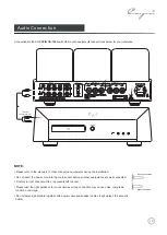
Cayin CS-100A User Manual Download Page 13

12

Audio Connection

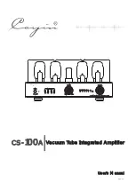
Connection method of 

CAYIN CS-100A

 with other audio equipments take pictures below for your reference.

Wrong connection

Right connection

NOTE

:

•  Please  refer  to  the  manual s  of  other  connected  equipments  during  the  installation.

•  Do  not  insert  the  power  cord  in to  the  main  socket  before  all  other  equipments  are  well  connected. 

•  R  refers  to  right  channel  while  L  represents  left  channel.

•  Please  take  the  right  guidance  for  connection  as  wrong  connection  may  cause  noise,  low-grade 

function  or  damage.

• 


Do  not  fasten  signal  cable  together  with  power  cable  and  speaker  cables. It  will  worsen  the  acoustic  

fidelity.

L E F T O U T P U T

R I G H T O U T P U T

I N P U T

L I N E

2

L I N E

1

L I N E

3

P R E

-

I N

T U B E S E L .

E L

3 4 

K T

8 8 

MO D E L


C S


-


1 0 0

A

S E R

.

N O

. :

VA C U U M T U B E I N T E G R AT E D A M P L I F I E R

Z H U H A I S PA R K E L E C T R O N I C E Q U I P M E N T C O . , LT D .

S U B O U T

O U T P U T

2

1

To audio

output terminal

Summary of Contents for CS-100A

Page 1: ...e Integrated Amplifier CS A 100 A1 POWER ON OFF A2 A4 A3 B1 B2 B4 B3 V O L U M E M I N M A X SELECTOR VACUUM TUBE INTEGRATED AMPLIFIER CS 100A BIAS SELECTOR TR UL LINE1 PRE IN LINE2 LINE3 REV 1 1 User...

Page 2: ...the tubes Before installation and operation please remove these foams to avoid any risks Vacuum Tube 1 Table of Contents Package Contents 2 Product Features 3 Safety Precautions 3 Specifications 4 Ma...

Page 3: ...indicates on the rear panel Too low or too high voltage may cause problem Please contact our company or our local agent if you ve found improper voltage Recommendation Keep all packing materials for f...

Page 4: ...ts per channel in Class AB Ultra linear mode Fifty watts per channel in Triode mode push pull amplifier design 6SN7GTB voltage amplification stage 12AU7EH phase invertor and voltage amplification 12BH...

Page 5: ...ure 0 40 Moisture 20 80 Storage Condition Temperature 20 70 Moisture 20 90 To reduce the risk of electric shock do not remove the cover No user serviceable parts inside Refer servicing to qualified se...

Page 6: ...The warranty doesn t extend to any product that has been opened by you without permission of our company Maintenance 5 NOTE Use the soft dry cloth to clean up the chassis regularly Do not use any chem...

Page 7: ...s the same as required We are not responsible for damage caused by misuse of unsuitable voltage 6 Connection of power cord Connect the speaker cables and signal cable first and then insert the power c...

Page 8: ...2 B3 B4 Used to select corresponding tube for bias adjustment You can hear sound from LINE2 when LINE2 indicator is on You can hear sound from LINE3 when LINE3 indicator is on You can hear sound from...

Page 9: ...o the Tube Replacement on page 11 find out what types of tubes you can use for replacement 2 Tube Sel on the rear panel must be turned to position KT88 if you are going to use KT88 series of tubes for...

Page 10: ...After all have been adjusted do it one more time to make sure all the bias level of A1 A2 A3 and A4 are the same Sample of bias adjustment for power tube A1 1 Turn the Bias Selector Switch A1 to its o...

Page 11: ...3 Mute Button 4 Volume Control Selector 1 2 3 4 Effective Distance about 6m Don t drop the remote control Keep the remote control dry Replace the batteries timely Don t mix new and old batteries toget...

Page 12: ...ifier over 15cm s distance to the surrounding walls Do not place the machine near heat sources such as radiators heat registers or other products that Installation 11 Please make sure local voltage le...

Page 13: ...ents are well connected R refers to right channel while L represents left channel Please take the right guidance for connection as wrong connection may cause noise low grade function or damage Do not...

Page 14: ...the terminal knob 2 Insert the speaker cable 3 Screw the terminal knob Connect the speaker cables with the amplifier after it is well connected with the speakers Connect both of the speakers to make...

Page 15: ...al for future reference Warning Signs Don t tear off or rub off the serial number Operation Do the operations as you are instructed in the Manual Parts If you are going to use parts not supplied by ou...

Page 16: ...ndicator is ON Volume is at ZERO Turn up the Volume NO signal input Check the function of the sound source Check the input selection and switch to the proper input Sound Distortion High input signal l...

Page 17: ...00B 2A3 etc 4 pin vacuum tubes Instructions to Change and Install the vacuum tubes To install a four pin vacuum tube please pay attention to the thickness of differnet pins of the vacuum tube and the...

Reviews: