background image

18

AUTO

:Automatic training

CONST

:Isopower training

INTVL

:Interval training

HILL

:Hill profile training

MANUAL

:Manual training

TEST

TIME 

AUTO

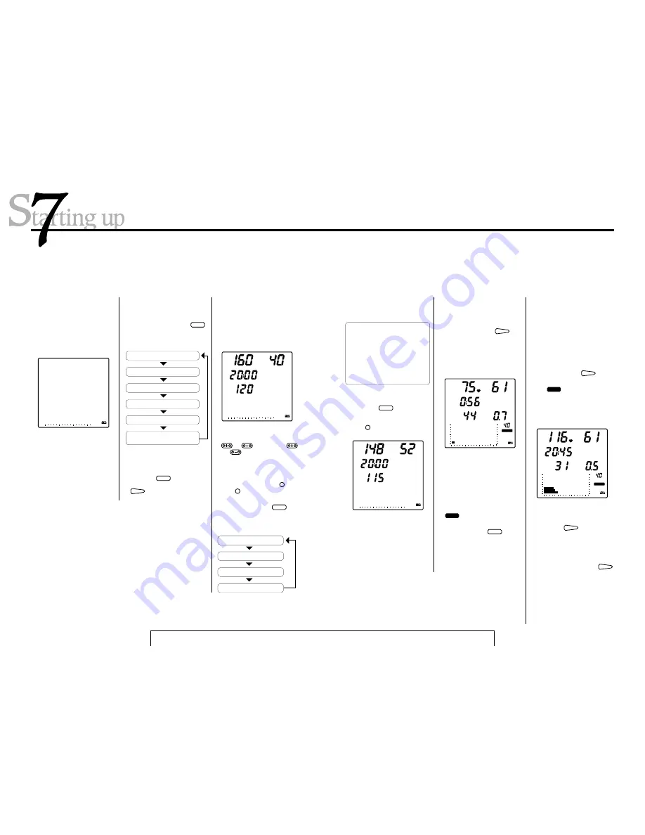
1. Switch on power supply

• Plug in the AC adaptor and turn

on the switch at the rear of the
main body.

• In the screen "AUTO" appears

blinking.

2. Select a training program

• With each press of the 

MODE

button, the flashing indicator
moves from one mode to another
in the following order.

3. Input training conditions

• The screen display will change to

the one shown in the diagram
here, with the number "40" flash-
ing.

Using your Cateye Ergociser™ without a data card

• On your first ride, you tried the

hill profile training. This time
choose "AUTO" as example.

• Press the

MODE

button until

"AUTO" flashes again, then press

ADV

 to lock in your choice.

TIME 

PLL

TM

TPL

AGE

min:sec

bpm

AUTO

• You can raise or lower the flashing

number by pressing either the

or

button. The

and

buttons change the tens

column and the ones column of
each number separately. For ex-
ample, suppose you want to
change the displayed age number
from 40 to 52. Press +

10

once

and +

1

two times. Has the num-

ber changed to "52"?

• With each press of the

MODE

 but-

ton, the flashing indicator moves
from one item to another in the
following order.

:Aerobic power
measurement

AGE

PLL

(upper limit pulse rate )

TM

(training time)

TPL

(target pulse rate)

The red card you used on your first ride contains the data
to select the type and condition of training. Without using
this card, it is also possible to run through the same
operations using the buttons on the control unit.

19

Remark: Conditions vary ac-

cording to the training pro-
gram.
Upper limit pulse rate is auto-
matically determined from
your age, so there is no need
to revise this number yourself,
unless you have a particular
purpose.

• Let's try changing the displayed

target pulse rate from 120 to 115.

• Press the

MODE

button until

"120" is flashing. You want to re-
duce the number by five, so press
the –

1

button five times. Has

the number changed to "115"?

TIME 

COOL

kg·m

TM

min:sec

watt

kg·m

rpm

AUTO

5. At the end of training

• A buzzer will sound when the

training time you have set is fin-
ished. If you wish, you can con-
tinue training even after this
buzzer sounds.

• Whenever you want to stop train-

ing, before or after the buzzer
sounds, push the

ADV

button

once.

• The

COOL

symbol appears on

the screen and the pedal resis-
tance drops to the minimum of 0.5
kg·m. This is the cooling down
function, which lasts for a maxi-
mum of 5 minutes.

4. Start training

• When you have set all the training

conditions, press the 

ADV

 but-

ton. The printer will give a print-
out of training conditions. When
this printout is complete, the
screen display will change to the
one similar to what is shown be-
low. Then you can start pedaling.

• At this stage review your workout

data such as time and calorie con-
sumption.

• Press the

ADV

button once

more and the printer will give a
printout of calories expended,
then the display turns to the initial
state. (If you stay in the cool down
phase for a full five minutes, you
do not have to push the

ADV

button.)

• You should now understand how

to use the Model EC-1600 Cateye
Ergociser™. Once you get used to
the exerciser, you will probably
want to refer to the Operation sec-
tion for more detailed information
on functions, etc.

TIME 

WARM

kg·m

PLL

TM

min:sec

watt

kg·m

rpm

AUTO

• The automatic training, isopower

training, interval training and
manual training programs all have
a warm-up function. Pedal resis-
tance increases slowly until you
reach your target pulse rate (Au-
tomatic training) or for the first
three minutes (all others). While
the warm-up function is operating,

WARM

symbol will remain on the

screen.

• By pressing the

MODE

button

during the exercise, you can
switch the display from elapsed
time (TM min:sec) to calorie con-
sumption (EC   Kcal), and vice-
versa.

TIME 

PLL

TM

TPL

AGE

min:sec

bpm

AUTO

• The card is a tool for program

choice and setting training condi-
tions. It saves you the trouble of
setting the same training condi-
tions each time you use the exer-
ciser. For instructions on how to
make a card, please refer to page
42, "How to make a data card" in
the Operation section.

Summary of Contents for EC1600E

Page 1: ...R Cateye Ergociser MODEL EC 1600 OPERATING INSTRUCTIONS EC 1600 EC 16OO...

Page 2: ...ting the date 49 4 Printing mechanism 50 5 Trouble shooting and handling care 52 6 Warranty service and optional parts 54 7 Specifications 55 1 Assembling 6 2 Installing the control unit 8 3 Connectin...

Page 3: ...g numerical value by 1 For pedal torque kg m by 0 1 When selecting the gender specifies MALE and FEMALE During exercise increases or decreases pedal torque by 1 0 kg m increases or decreases pedal tor...

Page 4: ...and OPTION Fixing Screw Holes Cable Inlet Control Unit Handlebar MAIN UNIT Paper Case Handlebar Lever Handlebar post Outer Cover Handlebar post Inner Cover Adjusting Knob Crank Pedal Front Leg Leg pip...

Page 5: ...this AC adapter from the electrical outlet immediately after using and before cleaning WARNING To reduce the risk of burns fire electric shock or injury to persons 1 An AC adapter appliance should ne...

Page 6: ...n 7 Using your Ergociser without a data card Make sure all components are included in a package E C 1 6 O O C a te y e E rg o c is e r OP ER AT ING INS TR UC TIO NS R EC 1200 Operating Instructions Wa...

Page 7: ...andlebar post handlebar post knob loosen tighten screw leg pipe caster Front Hook the leg cover at the end of each leg and fix it in position with adhesive tape as illustrated Note When placing leg co...

Page 8: ...hat the date in the machine s memory is always correct even when the main power supply is turned off These batteries will last two years under conditions of nor mal use When the battery symbol lights...

Page 9: ...nge the position of the pulse sensor during the exer cise If the symbol frequently lights up during use remove once and re attach the pulse sensor Attach the cable clip to your clothes to prevent exce...

Page 10: ...Be sure to grasp the outer post cover and keep it in position when removing the post knob in order to avoid sudden drop that may cause damages to the unit Note 2 Do not lift outer post cover above th...

Page 11: ...when it is eligible for changing Now however the goal is to get you acquainted with Model EC 1600 so if you change any of the numeral values please return them to their original setting power switch...

Page 12: ...again WORK RATE 17 4 Interval training exercise relief periods By switching back and forth be tween exercise and relief periods of varying length interval training gives you the kind of program that p...

Page 13: ...mber changed to 115 TIME COOL kg m TM min sec watt kg m rpm AUTO 5 At the end of training A buzzer will sound when the training time you have set is fin ished If you wish you can con tinue training ev...

Page 14: ...ng index 2 Aerobic power measurement Physical fitness test 3 Auto training 4 Isopower constant load training 5 Interval training 6 Hill profile training 7 Manual training 8 Setting your own training p...

Page 15: ...e For a beginner for in stance it is recommendable to start with 160 age approx 30 50 depending on your age and gradually proceed to higher level such as 180 age approx 50 70 It would be ideal to aim...

Page 16: ...r people with a long history of exercise The following is a reference Settings should match your physical fitness level and purpose 25 PWC max Pedal Torque kg m PWC max Pedal Torque kg m 50 rpm 70 rpm...

Page 17: ...pending on your pulse rate at that time The increased torque of 2nd and 3rd stages will be indicated in dots time after time in the graphic part 27 The buzzer sounds ten minutes later and the test res...

Page 18: ...n the Ergociser EC 1600 MOU is calculated based on the maximum physical work capacity PWC max explained below assuming that 1 litre of oxygen corresponds to 5 0 Kcal and the human body efficiency rate...

Page 19: ...ose to the target pulse rate 31 TIME kg m TM min sec watt kg m rpm AUTO TIME COOL kg m TM min sec watt kg m rpm AUTO If the 5 minute cool down phase has elapsed or if you press the ADV button the buzz...

Page 20: ...is set OFF There is no graphic display yet in the LCD You can increase or decrease the blinking numeric by pressing the buttons Press the MODE button to change the blinking numeric 33 After the WARM s...

Page 21: ...art Program Start Warm Up 4 3 After setting your conditions adapt the earlobe pulse sensor and depress ADV button to start program 35 TIME kg m TM min sec watt kg m rpm INTVL TIME COOL kg m TM min sec...

Page 22: ...g numeric by pressing the buttons Press the MODE button to change the blinking numeric 1 Select the Hill Profile Training Program For program selection see the Starting up section page 18 2 Input Cond...

Page 23: ...ss the ADV button to start the program instead of just pressing the ADV button you can skip the warm up phase and start the exercise at the preset pedal torque from the scratch 4 Start Warm Up 3 Start...

Page 24: ...d level of the blinking row Pedal resistance will be displayed in both numerical value and dot pattern Set your preferred torque value in the range from 0 5 kg m to the maximum of 4 0 kg m Having set...

Page 25: ...EST A B C D E F G H I 9 8 7 6 5 4 3 2 1 0 MANU HILL INTVL AUTO CONST TEST A B C D E F G H I 9 8 7 6 5 4 3 2 1 0 MANU HILL INTVL AUTO CONST TEST A B C D E F G H I 9 8 7 6 5 4 3 2 1 0 MANU HILL INTVL AU...

Page 26: ...l computer control via an RS232C terminal 2 Using chestbelt heart rate sensor 3 Setting the date 4 Printing mechanism 5 Troubleshooting and handling care 6 Warranty service and optional parts 7 Specif...

Page 27: ...DH 2 During Exercise Address Data Function 1 B code Hexadecimal 42H 2 4 digit numeric Elapsed time 2 digits minute 2 digits second 6 4 digit numeric Calorie consumption 10 3 digit numeric Wattage 13 2...

Page 28: ...ntact with your body at the center For further information please refer to the Manual enclosed in the Wireless Heart Rate Sensor Kit an optional item Chestbelt heart rate sensor adapted in position Di...

Page 29: ...T MODE ADV 6 Holding the edge of the thermal paper coming out of the paper guide pull it out and pass it under the printer cover Close the printer cover and draw the paper until the paper edge entirel...

Page 30: ...ensor cable proves to be damaged replace the whole pulse sensor with a new one Is the pulse sensor correctly at tached to your earlobe Is the sensor plug completely in serted into the sensor jack Prob...

Page 31: ...per 57mm x 25m roll Data input system Data card Use specified cards only and buttons Pulse sensor Earlobe pulse sensor with special noise reducing system Exercise programs Program Specifications Aerob...

Page 32: ...CO LTD R 0689131 E 2 8 25 Kuwazu Higashi Sumiyoshi ku OSAKA 546 0041 JAPAN PHONE 81 6 6719 7781 FAX 81 6 6719 2362...

Reviews: