background image

11   

DME-9724HM 

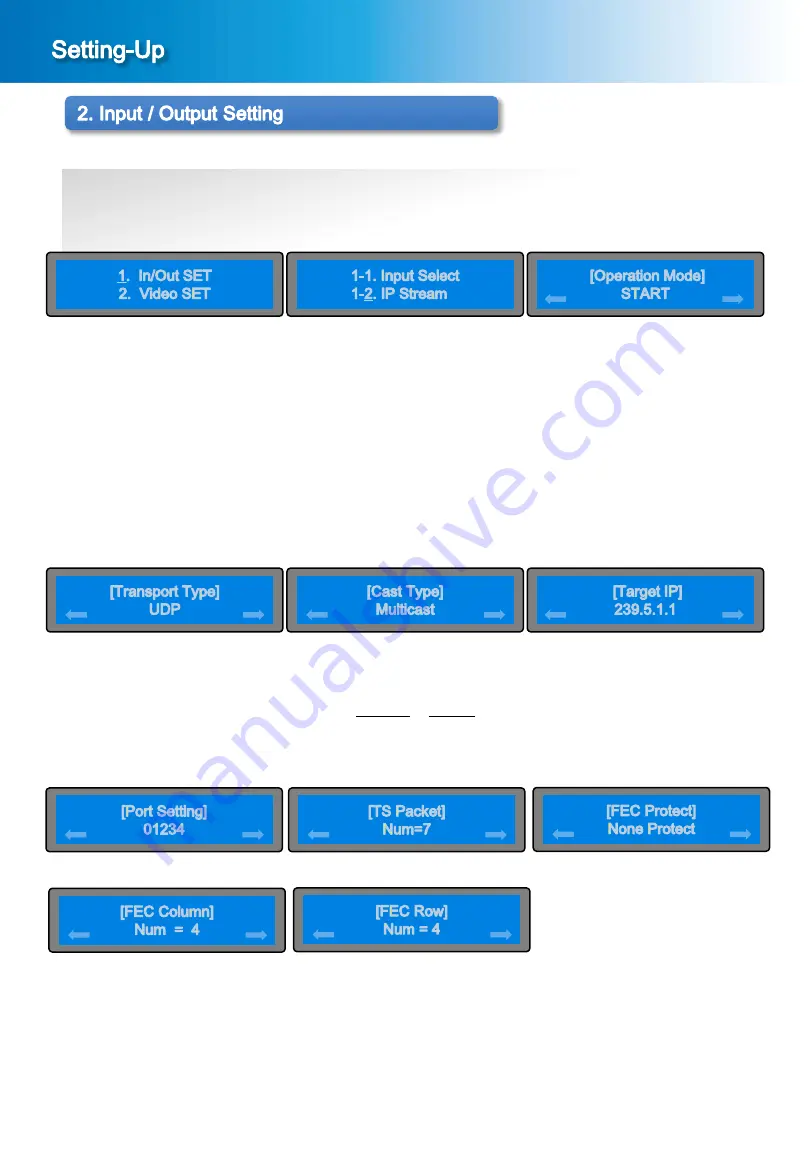
② Setting screen of IP Stream 
In the menu screen of the [Picture 2-1], press the < button or > button to bring it on “1. In/Out SET” and 
press the ENTER button, then the sub menu screen will be displayed as shown in the [Picture 2-5]. 
In the sub menu screen of the [Picture 2-5], press the ENTER button to bring it on “1-2. IP Stream”, then the 
setting screen of IP Stream will be displayed as shown in the [Picture 2-6] START or STOP. 
 
③ Setting of  Operation Mode 
In the menu screen of the [Picture 2-6], If press the ENTER button in the START status, screen  such as  
lower part appears in order. If selects the Stop, stops the IP stream.  
If select the Start, then press the ENTER  button, proceed to [Picture 2-7]. 


①  When  the  MENU  button  and  the  ESC  button  is  pressed  simultaneously  in  the  main  screen 
      [Picture 1-2], a menu screen will be displayed as shown in the [Picture 2-1]. 

[Picture 2-1] Menu Screen 

[Picture 2-5] Sub Menu Screen 

2-2. Setting of IP Stream 

[

Picture 2-6] Setting of IP Stream 

[

Picture 2-9] Setting of Target IP 

[Picture 2-8] Setting of Cast Type 

[Picture 2-7] Setting of Transport Type 

④ In the screen of the [Picture 2-7], select the UDP or RTP. If press the ENTER button,  proceed to [Picture 2-8]. 
⑤ In the screen of the [Picture 2-8], select the Multicast or Unicast. If press the ENTER button, proceed to  
     [Picture 2-9]. 
⑥ In the screen of the [Picture 2-9], set up the Target IP using the <, >, ∧, ∨  button. If press the  ENTER button,  
     proceed to [Picture 2-10].


[Picture 2-11] Setting of TS Packet 

[Picture 2-10] Setting of Port Setting 

⑦ In the screen of the [Picture 2-10], can select to 1~65535. If press the ENTER button, proceed to [Picture 2-11].  

⑧ In the screen of the [Picture 2-11], can select to 1~7. Press the ENTER button to proceed to [Picture 2-12]  

⑨ In the screen of the [Picture 2-12], can select to “None Protect” or “1D Protect”. Press the ENTER button to  

     proceed to [Picture 2-13] 

⑩ In the screen of the [Picture 2-13], can select to 1~31. Press the ENTER button to proceed to [Picture 2-14]  

⑪ In the screen of the [Picture 2-14], can select to 1~31. Press the ENTER button to save the setting  of IP Stream.  

 
    Press the ESC button to cancel the setting of IP Stream. 
    Press the ENTER button to save the setting value.  

[Picture 2-12] Setting of FEC Protect 

[Picture 2-13] Setting of TS Packet 

[Picture 2-14] Setting of FEC Protect 

Summary of Contents for DME-9724HM

Page 1: ...MPEG 2 4 AVC HD Encoder DME 9724HM Operation Manual Version 1...

Page 2: ...r our company where you have purchased our product Please keep the box etc used for packaging well so you can be eligible for the after sale service The period of keeping parts for after service of th...

Page 3: ...h as it will be very dangerous if the child puts it on the head If products are dismantled for repair by an unauthorized person you may not be eligible for the maintenance and repair service Hence in...

Page 4: ...4 DME 9724HM Release History Edit Date Approved by Description 0 2014 01 First Version 1...

Page 5: ...f the product not following the instructions specified in this users manual In case the rated voltage or frequency specified in this users manual is not used In case failure occurs while dismantling a...

Page 6: ...6 3 6 Setting of Sync Loss 17 4 Audio Setting 4 1 Setting of Audio Map Select 18 4 2 Setting of Audio Encoder 19 4 3 Setting of Audio Bitrate 20 4 4 Setting of Audio Signal Volume Level 21 4 5 Setting...

Page 7: ...digital mode is normally inputted IP OUT LED Lights up when IP OUT signal is normally outputted MENU Button Used to switch screen to upper menu previous screen ESC Button Used to clear selection or ca...

Page 8: ...Signal Input Terminal HDMI Input A terminal connecting HDMI signal Input ASI signal Input Terminal ASI Input TS Signal input terminal of DVB ASI method Component Composite Signal Input Terminal A term...

Page 9: ...hen booting is completed the main screen will be displayed as shown in the Picture1 2 In the menu screen of the Picture 2 1 press button or button to confirming the Setting values Following informatio...

Page 10: ...reen of Audio Input Signal Likewise select SDI or HDMI ANALOG SPDIF AES EBU using the button or button then press the ENTER button to save the set value Press the ESC button to cancel the setting of V...

Page 11: ...ast Type Picture 2 7 Setting of Transport Type In the screen of the Picture 2 7 select the UDP or RTP If press the ENTER button proceed to Picture 2 8 In the screen of the Picture 2 8 select the Multi...

Page 12: ...to return to upper menu previous screen The video encoding bit rate is set at 18 0Mbps for release When the MENU button and the ESC button is pressed simultaneously in the main screen Picture 1 2 a me...

Page 13: ...enu Screen Picture 3 6 CBR Mode Picture 3 8 VBR Mode Picture 3 5 Sub Menu Screen Picture3 9 Video Bit Rate Setting of Bitrate Mode In the menu screen of the Picture 3 1 press the button or button to b...

Page 14: ...the screen of the Picture 3 10 set up the IP IBBP IBP using the button or button then press the ENTER button to save the set value Setting of GOP Size In the screen of the Picture 3 10 select the GOP...

Page 15: ...ing of Profile Type In the menu screen of the Picture 3 12 press the button or button to select a desired Profile Type and press the ENTER button to save the set value Press the ESC button to cancel t...

Page 16: ...spect Ratio In the menu screen of the Picture 3 13 press the button or button to select a desired Aspect Ratio and press the ENTER button to save the set value Press the ESC button to cancel the setti...

Page 17: ...ton then the setting screen of Sync Loss Screen will be displayed as shown in the Picture 3 17 Color Bar or Black In the screen of the Picture 3 16 set up the Color Bar or Black using the button or bu...

Page 18: ...displayed as shown in the Picture 4 3 Setting of Map Select In the screen of the Picture 4 3 select the Audio Off Stereo 1 2CH Stereo 2 4CH Stereo 3 6CH Stereo 4 8CH 5 1CH using the button or button...

Page 19: ...e 1st Enc Type 2nd Enc Type 3rd Enc Type and 4th Enc Type using the button or button then press the ENTER button to save for 4 Audio Encoder Type Setting of 1st 4th Audio Encoder Type In the screen of...

Page 20: ...ate Setting of Audio Bit rate In the menu screen of the Picture 4 6 press the button or button to have it indicate the desired encoding bit rate and press the ENTER button to save the Audio Bit rate P...

Page 21: ...ume 2nd Volume 3rd Volume and 4th Volume using the button or button then press the ENTER button to save for 4 Audio Volume Setting of the Audio Signal Volume In the menu screen of the Picture 4 7 pres...

Page 22: ...ture 4 8 select the 1st Channel 2nd Channel 3rd Channel and 4th Channel using the button or button then press the ENTER button to save for 4 Audio Channel Setting of the Audio input channel In the men...

Page 23: ...utton or button then press the ENTER button to save for 4 Audio Delay Setting of Audio Delay In the screen of the Picture 4 11 press the button or button to have it indicate the desired audio signal d...

Page 24: ...n the sub menu screen of the Picture 4 12 select the 1st Bypass 2nd Bypass 3rd Bypass and 4th Bypass using the button or button then press the ENTER button to save for 4 Audio Bypass Setting of Bypass...

Page 25: ...ess the button or button to bring it on Internal PSIP and press the ENTER button then the sub menu screen will be displayed as shown in the Picture 5 4 Press the ENTER button after you select the Inte...

Page 26: ...main screen Picture 1 2 the menu screen shown in the Picture 5 1 will be displayed Picture 5 1 Menu Screen Picture 5 2 Sub Menu Screen 5 2 PID Setting Picture 5 9 Setting of PMT PID Picture 5 10 Sett...

Page 27: ...ting using the button and then press ENTER button then the setting screen will be displayed as shown in the Picture 6 6 In the screen of the Picture 6 6 set up Subnet setting using the button and then...

Page 28: ...creen of System Delay will be displayed as shown in the Picture 6 7 Setting of System Delay In the screen of the Picture 6 10 select the Max and U Low using the button or button and then press ENTER b...

Page 29: ...if used are connected to the proper outlets for the given model as shown below Web controller only operate in same network of device 7 1 Install 1 2 The Web controller runs on any system that supports...

Page 30: ...vice this is used to check whether or not the Up Grading was normally and correctly performed Checking of Firmware Version In the screen of the Picture 6 9 confirm the date of up grade or the firmware...

Page 31: ..._Search_Tool_V 122 exe file is running As Figure 7 2 is shown click on the Search button and then confirm the F W version IP Address and Subnet Mask and Gateway As Figure 7 3 is shown you can copy MSW...

Page 32: ...e Search function is used to search all modules existing on the same LAN By using UDP broadcast all modules on the same subnet will be searched The searched module is displayed as MAC address in the B...

Page 33: ...25801 This is the factory set password of your device User Login After change the password enter new password and click on LOGIN Login use name USER Login password XXXXX This is the factory set ID of...

Page 34: ...onds 8 2 System Setting Picture 8 2 System Tab Screen SYSTEM IN OUTPUT VIDEO AUDIO PSIP PID IP STREAM TCP IP user Hello LOGOUT DME 9724HM HD Encoder SYSTEM Information Setting EQUIPMENT ID DME 9724HM...

Page 35: ...PDIF AES EBU After making changes click on the APPLY button to apply the new settings It will takes about 10 seconds 8 3 Input Output Setting Figure 8 3 Input Output Tab Screen SYSTEM IN OUTPUT VIDEO...

Page 36: ...Video Setting Figure 7 8 Video Tab Screen SYSTEM IN OUTPUT VIDEO AUDIO PSIP PID IP STREAM TCP IP user Hello LOGOUT DME 9724HM HD Encoder VIDEO Information Setting Video Encoder Type H 264 MPEG 2 Vide...

Page 37: ...Hello LOGOUT DME 9724HM HD Encoder AUDIO Information Setting Audio 1 Audio 2 Audio 3 Audio 4 SETTING Figure 8 5 Audio Tab Screen SETTING SETTING SETTING Audio 1 Audio 2 Audio 3 Audio 4 To setting for...

Page 38: ...ass After making changes click on the APPLY button to apply the new settings To other Audio channel setting click on the BACK button and then the setting tab will be displayed as shown in the Picture...

Page 39: ...changes click on the APPLY button to apply the new settings It will takes about 10 seconds 8 7 PSIP Setting SYSTEM IN OUTPUT VIDEO AUDIO PSIP PID IP STREAM TCP IP user Hello LOGOUT DME 9724HM HD Encod...

Page 40: ...s 8 8 PID Setting SYSTEM IN OUTPUT VIDEO AUDIO PSIP PID IP STREAM TCP IP user Hello LOGOUT DME 9724HM HD Encoder PID Information Setting PSIP PID Video PID Audio PID 1ST Audio PID 2nd Audio PID 3rd Au...

Page 41: ...t will takes about 10 seconds 8 9 IP Stream Setting SYSTEM IN OUTPUT VIDEO AUDIO PSIP PID IP STREAM TCP IP user Hello LOGOUT DME 9724HM HD Encoder IP STREAM Information Setting Operation Off On Transp...

Page 42: ...new settings It will takes about 10 seconds 8 10 TCP IP Setting SYSTEM IN OUTPUT VIDEO AUDIO PSIP PID IP STREAM TCP IP user Hello LOGOUT DME 9724HM HD Encoder TCP IP Information Setting Main DHCP Sett...

Page 43: ...ic objects near around the product Please unplug the power plug and reconnect it Can not see the screen and hear the voice Picture quality is bad and sway Check the connection status of the input sign...

Page 44: ...pin input Configuration There are two sets of Connector provided Analog Audio Connectors must be connected in order If 1 stereo Use Stereo 1 If 2 stereos Use Stereo 1 2 If 3 Stereos Use Stereo 1 2 3...

Page 45: ...direct management Information Y M D Repair detail and Explanation for usage Free or Paid Service Where repaired Engineer Signa ture Repair Inspection Details After receiving service make sure to recor...

Page 46: ...www castwin com Head Office Laboratory 40 12 Teheran ro 38 gil Gangnam gu Seoul Korea 135 920 Phone 82 2 6005 9118 Fax 82 2 3453 8338 E mail castwin castwin com...

Reviews: