


V-R100
– 29 –
4. Status
[Function]
Switches and sensors tests.
[Procedure]
(1) Touch "4" on the panel. Display indicates the screen shown below.
Note: Push "INIT" switch lastly as it is for showing the tes results.
Quit this screen by INIT-SWITCH
PAPER SET
HEAD UP
PAPER 80mm
DRAWER #1 CLOSE
DRAWER #2 CLOSE
DISP-SW RELEASE
INIT-SW RELEASE
PAPER
Paper is in: SET
No paper is set: END
HEAD
Paper holder is free: UP
Paper holder is locked:
DOWN
PAPER
Paper size
DRAWER #1
Drawers statuses
DRAWER #2
DISP-SW RELEASEt Shows "PUSH" when
"Main display OFF/ON
switch" is pushed.
INIT-SW RELEASE
Shows "PUSH" when
"INIT" switchi is pushed.
(2) Finally, push "INIT" switch.
(3) Display shows "Push Switch OK: DISP-sw or NG: INIT-sw".
(4) Push corresponding switch described below to check the test result.
In case of OK: Display resumes DIAG MENU by pushing "Main display OFF/ON" switch.
In case of NG: Display indicates "sts ERROR 1" by pushing "INIT" switch. Display resumes
DIAG MENU by pushing "Main display OFF/ON" switch.
5. Main LCD
[Function]
Checks the LCD.
[Procedure]
(1) Touch "5" on the display panel.
(2)
By touching "5" repeatedly, display changes;
"Black" > "White" > "Red" > "Green" > "Blue" > "Check" > "Reversed check" > "Backlight Off" "
> "Reversed check with backlight on (duty ratio 5%)"
> "Reversed check with backlight on (dury ratio 50%)"
> "Reversed check with backlight on (duty ratio 100%)"
(3) Display panel indicates "Push Switch OK: DISP-sw or NG: INIT-sw".
(4) Push corresponding switch described below to check the test result.
In case of OK: Display resumes DIAG MENU by pushing "Main display OFF/ON" switch.
In case of NG: Display indicates "mlcd ERROR 1" by pushing "INIT" switch. Display resumes
DIAG MENU by pushing "Main display OFF/ON" switch.
Summary of Contents for V-R100
Page 1: ...SERVICE MANUAL Ver 3 Aug 2013 V R100 EX 841 OCT 2011 ...
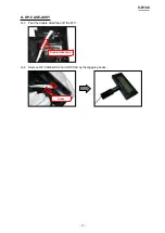
Page 13: ...V R100 10 A 10 Undo three screws and disconnect three ground wires Screw S12 Screws S3 ...
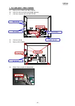
Page 43: ...V R100 40 5 3 PCB E840 1 PCB ...
Page 44: ...V R100 41 E840 E61 PCB E840 E62 PCB E840 IOC PCB ...
Page 45: ...V R100 42 E840 E22 PCB E840 COM PCB E840 ETH PCB E840 E64 PCB E840 E63 PCB E840 PRN PCB ...


