— 29 —
8
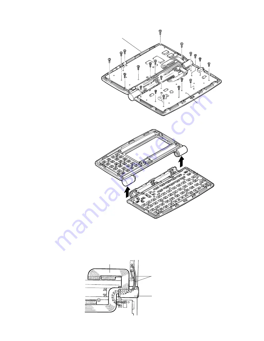
Remove screws on PCB shown above then remove PCB ass’y.
Main PCB
(9 screws)
Keyboard PCB
(11 screws)
9
Separate upper cabinets.
REMARK:
Heat seal and wires must be placed inside of the hinge in order for the Lower cabinet (keyboard) to fit
into place.
If heat seal and wires are placed improperly, they are damaged.
Lower cabinet
Heat seal
Wires (Black/Red)
Hinge
Summary of Contents for SF-5590SY
Page 19: ... 19 6 SCHEMATIC DIAGRAMS 6 1 MAIN PCB ASS Y A342054 1 4 CPU ...
Page 20: ... 20 6 1 MAIN PCB ASS Y A342054 2 4 ...
Page 21: ... 21 6 1 MAIN PCB ASS Y A342054 3 4 ...
Page 22: ... 22 6 1 MAIN PCB ASS Y A342054 4 4 ...
Page 23: ... 23 6 2 KEYBOARD PCB ASS Y A342055 1 3 COM PORT BUZZER ...
Page 24: ... 24 POWER SUPPLY 6 2 KEYBOARD PCB ASS Y A342055 2 3 ...
Page 25: ... 25 6 2 KEYBOARD PCB ASS Y A342055 3 3 ...
Page 33: ...MA0900571A ...


