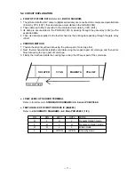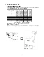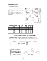
— 23 —
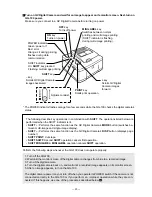
Turn on QV Digital Camera and wait for an image to appear on its monitor screen. Next, turn on
QG-100 power.
Make sure you connect to a QV Digital Camera before turning on power.
OFF key
Turns off power.
ON key
Turns on power.
POWER indicator
Green: power on*
Red: error
Orange: Lit during printing,
flashes during data
communication
SHIFT indicator
On: SHIFT key pressed
Flashing: multi-image printing
SHIFT key
– key
Scrolls QV Digital Camera
images backward.
Adjusts contrast.
PRINT key
Starts print operation.
+ key
Scrolls QV Digital
Camera images
forward.
MINI LABEL key
Switches between normal
printing and multi-image printing
(SHIFT indicator is flashing
during multi-image printing).
* The POWER indicator flashes orange for a few seconds while the QG-100 checks the digital camera’s
status.
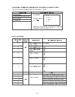
The following describe key operations in combination with SHIFT. The operations listed below are
performed when the SHIFT indicator is lit.
• SHIFT +: Performs the same function as the QV Digital Camera’s MODE button (switches be-
tween multi-image and single-image display).
• SHIFT –: Performs the same function as the QV Digital Camera’s DISP button (displays page
number).
• SHIFT PRINT: Cuts tape.
• SHIFT SHIFT: Second SHIFT operation cancels first operation.
• SHIFT MINI LABEL: MINI LABEL operation cancels SHIFT operation.
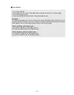
Perform the following steps whenever the QG-100 does not operate properly.
1. Turn off the QG-100.
2. Wait until the monitor screen of the digital camera changes from blue to a recorded image.
3. Turn of the digital camera.
4. Turn the digital camera back on, and wait until a recorded image appears on its monitor screen.
5. After an image appears, turn on the QG-100.
The digital camera power may not turn off when you operate its POWER switch if the camera is not
connected correctly to the QG-100 or if you perform an improper operation while they are con-
nected. If this happens, use one of the procedures described below .
3
5
Summary of Contents for QG-100
Page 1: ...JULY 1996 without price QG 100 ZX 568 ...
Page 4: ... 2 3 BLOCK DIAGRAM ...
Page 5: ... 3 4 SCHEMATIC DIAGRAMS 4 1 Wiring Diagram ...
Page 6: ... 4 4 2 Main PCB Z568 1 1 2 ...
Page 7: ... 5 4 3 Main PCB Z568 1 2 2 ...
Page 8: ... 6 4 4 Power PCB Z568 S1 ...
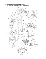
Page 32: ... 30 11 EXPLODED VIEW DISASSEMBLY VIEW 11 1 EXPLODED VIEW Z568 1 ASS Y COMPONENTS ...
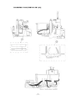
Page 34: ... 32 11 2 DISASSEMBLY VIEW PRINTER UNIT 1 2 ...
Page 35: ... 33 DISASSEMBLY VIEW PRINTER UNIT 2 2 ...
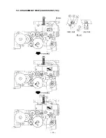
Page 37: ... 35 11 3 DISASSEMBLY VIEW CHASSIS UNIT 1 2 ...
Page 38: ... 36 DISASSEMBLY VIEW CHASSIS UNIT 2 2 ...
Page 40: ... 38 11 4 DISASSEMBLY VIEW CHASSIS ASS Y 1 2 ...
Page 41: ... 39 DISASSEMBLY VIEW CHASSIS ASS Y 2 2 ...
Page 43: ... 41 11 5 DISASSEMBLY VIEW HEAD HOLDER ASS Y 1 2 ...
Page 44: ... 42 DISASSEMBLY VIEW HEAD HOLDER ASS Y 2 2 ...
Page 46: ... 44 11 6 DISASSEMBLY VIEW PLATEN ASS Y ...
Page 48: ... 46 11 7 DISASSEMBLY VIEW CASSEETTE CASE ASS Y ...
Page 50: ... 48 11 8 DISASSEMBLY ASS Y MOTOR CHASSIS ASS Y ...
Page 51: ......
Page 52: ...MA0900461A ...


