background image

— 14 —

O

RHYTHM

P

DRAWBAR ORGAN

Q

DSP

R

PIANO SETTING

S

Cursor key Up

T

Cursor key Right

U

Cursor key Down

V

Cursor key Left

W

EXIT

X

AUTO HARMONIZE

Y

SPLIT

Z

LAYER

Initial Setup

1. Connect an AC adaptor.
2. Connect a Sustain pedal.
3. "Main" volume: MAX.

NOTE: If there is no pedal or MIDI cable, pedal or MIDI check can be skipped.

 How to start diagnostic program

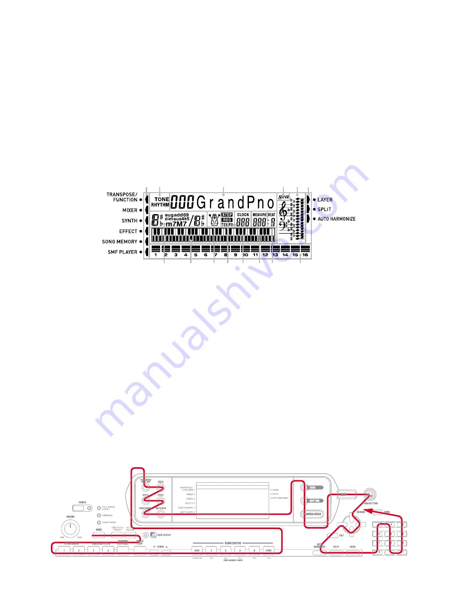
1. Press the “POWER” button while pressing the “Cursor key Up” and “Cursor key Down” buttons.
2. Release the “POWER” button first while still pressing the “Cursor key UP” and “Cursor key Down”

buttons. After “000 Sy.Gr Pno” appears, release the “Cursor key UP” and “Cursor key Down”
buttons. “TEST 705” appears on the LCD.

NOTE: Refer to the figure below for the LCD messages that appear during the diagnostic program.

1

MODE

2

ONE TOUCH PRESET

3

ACCOMP VOLUME

4

INTRO/ENDING 1

5

INTRO/ENDING 2

6

VARIATION/FILL-IN 1

7

VARIATION/FILL-IN 2

8

SYNCHRO/FILL-IN NEXT

9

START/STOP

@

TEMPO

A

TEMPO

B

BANK

C

REGISTRATION 1

D

REGISTRATION 2

E

REGISTRATION 3

F

REGISTRATION 4

G

STORE

H

TRANSPOSE/FUNCTION

I

MIXER

J

SYNTH

K

EFFECT

L

SONG MEMORY

M

SMF PLAYER

N

TONE

DIAGNOSTIC PROGRAM

 Diagnostic program

1. Button check

1

Press “DSP” button. Display indicates 

3

 “MODE”.

2

Press buttons in the following order.

NOTE:

 NG sound sounds when a button is defective or buttons are pressed in a wrong order.

LCD message appears in the area 

3

OTP

ACMP VOL

INT/END1

INT/END2

VAR/FIL 1

VAR/FIL 2

SYNCHRO

STRT/STP

TEMPO/DW

TEMPO/UP

BANK

REGIST 1

REGIST 2

REGIST 3

REGIST 4

STORE

TRN/FUNC

MIXER

SYNTH

EFFECT

SONG

SMF

TONE

RHYTHM

Message on LCD

Message on LCD

Message on LCD

Message on LCD

1 2

3

4 5 6

7

8

9

0

A

B

C

D

DRAWBAR

DSP

PIANO

UP

RIGHT

DOWN

LEFT

EXIT

HARMO

SPLIT

LAYER

0

[

0 buttons

\

1 buttons

]

4 buttons

`

7 buttons

a

8 buttons

b

5 buttons

c

2 buttons

d

- buttons

e

+ buttons

f

3 buttons

g

6 buttons

h

9 buttons

i

DEMO

1

4

7

8

5

2

-

+

3

6

9

DEMO

SW OK

[

\

]

^

T

U

S

V

W

Z

Y

X

G

F

E

D

C

B

A

0

9

8

7

6

5

4

1 2 3

H
J
L

I
K
M

i

Q

N
O

P

R

d

c

b

a

e

f

g

h

Summary of Contents for CTK-691

Page 1: ...ELECTRONIC KEYBOARD CTK 691 CTK 691 JUN 2003 Ver 2 Sep 2006...

Page 2: ...CONTENTS Page Specifications 1 Block Diagram 3 Circuit Description 4 Printed Circuit Boards 5 Disassembly 8 Diagnostic Program 14 Schematic Diagrams 17 Exploded View 22 Parts List 23...

Page 3: ...ction Songs 5 Recording Tracks 6 2 through 6 are melody tracks Recording Methods Real time step Memory Capacity Approximately 10 000 notes total for 5 songs Edit Function Equipped Demo Tunes 3 Synthes...

Page 4: ...mately 5 6 kg 12 3lbs without batteries The same memory area is used to store waveform data accompaniment data and SMF data ELECTRICAL Current drain with 9 V DC No sound output 1200 mA 20 Maximum volu...

Page 5: ...5V VD5 5V VA5 9V VCP APO ADIN Battery APO Cancellation Speakers L R Phones Output LOUT CONT ROUT AC Adaptor DC 9V Keyboard Buttons FLASH ROM 16MBit IC5 LH28F160BJHE BTL90 RAM 1Mbit IC12 CY62128VLL 70...

Page 6: ...1 G 5 1 A5 1 A 5 1 B5 1 E5 2 F5 2 F 5 2 G5 2 G 5 2 A5 2 A 5 2 B5 2 C6 1 C 6 1 D6 1 D 6 1 E6 1 F6 1 F 6 1 G6 1 C6 2 C 6 2 D6 2 D 6 2 E6 2 F6 2 F 6 2 G6 2 G 6 1 A6 1 A 6 1 B6 1 C7 1 G 6 2 A6 2 A 6 2 B6...

Page 7: ...5 PRINTED CIRCUIT BOARDS Main PCB M705 MA1M Top View Bottom View...

Page 8: ...6 Sub PCB M705 MA2M LCD PCB M705 LCD1M Top View Top View...

Page 9: ...7 CONSOLE PCB M705 CN2M Top View CONSOLE PCB M705 CN1M Top View CONSOLE PCB M705 CN4M CONSOLE PCB M705 CN3M Top View Top View...

Page 10: ...ttery 2 Remove 27 screws and then the upper case 3 Remove 5 screws 4 speaker cords 2 battery cords 3 connectors JC JG JH and then the PCB ASS Y MA2M Speaker cord BL Speaker cord W Speaker cord O Speak...

Page 11: ...the LCD ASS Y LCD1M Note Tighten the screws in the order from 1 to 6 when reassembling 1 2 3 4 5 6 Screws Screws Screws Connectors Connectors Connectors Note How to attach a HEAT SINK Insert aTRANSIST...

Page 12: ...Screws 6 Remove 3 screws connector JL and then the PCB ASS Y CN3M Connector 7 Remove 2 screws the volume knob and then the PCB ASS Y CN2M Volume knob Screws 8 Remove 22 screws and then the PCB ASSY C...

Page 13: ...ode D301 D302 D306 D303 D305 D301 D302 D307 9 Remove 13 screws and then the lower case Note Tighten the screw with the arrow mark in the figure first when reassembling Cushion D304 Note Mount LED on t...

Page 14: ...B ASSY KY1M KY2M 11 Remove the rubber keys Note Pay attention to the positions of the rubber keys as one of them has a different length Match the projections of the rubber keys with the holes of the l...

Page 15: ...13 12 Remove 21 screws and then the white keys 13 Remove the black keys Note Pay attention to the positions of the screw holes when reassembling...

Page 16: ...2 8SYNCHRO FILL IN NEXT 9START STOP TEMPO ATEMPO BBANK CREGISTRATION 1 DREGISTRATION 2 EREGISTRATION 3 FREGISTRATION 4 GSTORE HTRANSPOSE FUNCTION IMIXER JSYNTH KEFFECT LSONG MEMORY MSMF PLAYER NTONE...

Page 17: ...ROM check 1 Press INTRO ENDING1 button 2 OK sound must be audible 7 Flash memory bus check 1 Press INTRO ENDING2 button 2 OK sound must be audible 8 DSP RAM check 1 Press VARIATION FILL IN 2 button 9...

Page 18: ...If no TUNING METER this check can be skipped 1 Connect the TUNING METER to the phone jack 2 Press 8 button 3 The TUNING METER must indicate C 4 Disconnect the TUNING METER from the phone jack 13 APO c...

Page 19: ...17 SCHEMATIC DIAGRAMS Main PCB M705 MA1M...

Page 20: ...18 Sub PCB M705 MA2M...

Page 21: ...19 CONSOLE PCBs M705 CN1M CN2M CN3M CN4M...

Page 22: ...20 Display PCB M705 LCD1M...

Page 23: ...21 Keyboard PCBs JCM618T KY1M KY2M...

Page 24: ...22 EXPLODED VIEW 37 17 38 38 25 18 20 19 33 34 35 32 26 21 28 23 22 24 27 31 16 3 15 8 13 14 39 7 2 1 5 4 R 2 R 3 16 30 29 R 1 36 6 11 12 9 10...

Page 25: ...our spare parts department if you need these parts for refurbish 1 Prices and specifications are subject to change with out prior notice 2 As for spare parts order and supply refer to the GUIDEBOOK fo...

Page 26: ...IC201 10062671 IC LA4636 1 AV B IC202 203 21210072 IC NJM2068DD 2 AD B D201 202 23903021 DIODE SRT14 2 AF C D203 207 208 210 23153132 DIODE 1SS133T 77 4 AA C D204 10038115 DIODE MTZJT 775 6B 1 AA C D2...

Page 27: ...1V01 1 AA C N 22 10123853 RUBBER KEY B RJM502493 001V01 1 AE C N 23 10123855 RUBBER KEY C RJM502494 001V01 1 AB C N 24 10123859 RUBBER KEY D RJM502495 001V01 1 AE C N 25 10123862 RUBBER KEY E RJM50249...

Page 28: ...Ver 1 Dec 2005 Replacement of the PARTS LIST P25 Ver 2 Sep 2006 Replacement of the PARTS LIST P25 CASIO COMPUTER CO LTD Overseas Service Division 6 2 Hon machi 1 Chome Shibuya ku Tokyo 151 8543 Japan...

Reviews: