cashco POSR-2 Installation, Operation & Maintenance Manual Download Page 14

IOM-POSR-2

14

7.  Slowly pressurize the inlet of the main valve 

(MV) and pilot valve (PV) to 100 psig (6.9 Barg). 

NOTE:


If the pilot valve (PV) has any other 

range spring (15) above 5–15 psig (.34–1.03 
Barg), the test pressure can be raised to 200 
psig (13.8 Barg)

.

8.  Using a solution of leak detection fluid and 

water, apply a liberal amount of the solution to 
cover each external joint, including the thread ed 
fittings (20), tub ing (21) and the interconnecting 
pipe nipple (19) threaded con nec tions. Wait 
a minimum of five min utes to allow sufficient 
time for a leak to form bub bles. Repeat this 
procedure with a second five minute wait.

SECTION VIII

9.  Identify and mark any observed leakage. 

Dis as sem ble down to the point of leakage 
and determine the cause of the leak. Repair 
and reassemble per instructions in Section 
VI. Retest per Section VII.

10.  Shut off pressure to inlet connection of 

main valve (MV) and remove all leak testing 
equip ment. Reset the adjusting screw (19) 
back to its normal setpoint by rotating the 
screw (19) CCW (viewed from above) the 
same num ber of revolutions recorded in Ar ti cle 
6. pre vi ous, this subsection.

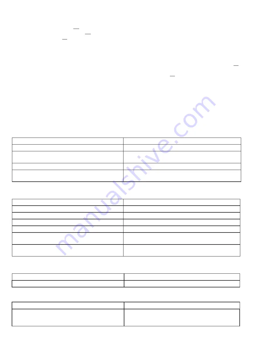
VIII. TROUBLE SHOOTING GUIDE


1.  Erratic or Noisy Operation.

Possible Cause

Remedy

a.

Wet steam or condensate at the inlet.

a.

Install a steam trap on the inlet side of the regulator.

b.

Clogged pilot valve screen.

b.

Clean or replace. Blowdown inlet drip leg. Install up-
stream strainer, if severe.

c.

Regulator oversized for flow conditions.

c.

Install correct size.

d.

Insufficiently sloped line.

d.

Move tap from top of pipe to side; or, increase sensing 
tube to 3/8" OD.


2.  Regulator won't maintain downstream set pressure.

Possible Cause

Remedy

a.

Valve undersized.

a.

Resize based on actual service conditions.

b.

Incorrect range spring.

b.

Replace range spring.

c.

Failed bellows.

c.

Replace bellows assembly.

d.

Failed piston seal ring.

d.

Replace seal ring.

e.

Pressure drop less than required 15 or 20 psid 
(1–1.4 Bard).

e.

Contact your Cashco Representative.

f.

Insufficiently sloped line.

f.

Move tap from top of pipe to side; or, increase sensing 
tube to 3/8" OD.

Possible Cause

Remedy

a.

Defective diaphragm.

a.

Replace diaphragm.


3.  Leakage through the pilot spring chamber vent hole.


4.  Excessive pressure downstream.

Possible Cause

Remedy

a.

Main valve or pilot plug not closing.

a.

Inspect the seating of the main valve and then the 
pilot plug seating. Clean or replace. Check seat 
gaskets; replace.

Summary of Contents for POSR-2

Page 1: ...et pressure gauge should be located approximatelytenpipediametersdownstream and within sight 5 All installations should include a downstream relief device if the inlet pressure could exceed the pressu...

Page 2: ...thepilotvalvesenses the reduced pressure and the pilot valve s SECTION III 7 In placing thread sealant on pipe ends prior to engagement assure that excess material is removedandnotallowedtoenterthere...

Page 3: ...SITION H POSITION VU Pilot valve and main valve shipped as two units Installer to connect between pilot valve and main valve for loading and supply tubes POSITION VD Pipe or tubing installed by custom...

Page 4: ...omabove untilflow begins 7 Continue to alternate slowly closing the bypassvalveandthenslowlyopeningtheinlet upstream block valve especially when the downstream piping system isn t pressurized If the o...

Page 5: ...close the inlet upstream block valve Close the outlet downstream valve only if regulator removal is required Close the needle valve on the pilot valve s sensing line 6 Most pilot operated valve operat...

Page 6: ...to remove the bellows 11 in the box below Number of revolutions required to remove bellows 11 ________________ Inspect the bellows 11 for a crack or joint failure where leakage is occurring Replace b...

Page 7: ...uld be protruding bellows 11 Invert bellows 11 with stem extension 10 into body 1 recess Allow stem extension 10 to fall into threaded opening for bellows 11 Align threaded portion of bellows 11 rotat...

Page 8: ...Never replace bolting 17 18 with just any bolting if lost Bolt heads and nuts are marked with specification identification markings Use only proper grades as replacements For the 1 through 2 main val...

Page 9: ...laxed before the stem nut 15 is fully removed 15 Pull cylinder 3 horizontally outwards to removal movingoverheadhoistasnecessary Set cylinder 3 aside 16 Using a needle nose pliers grasp outside lip of...

Page 10: ...ith a clean dry cloth 32 Place cylinder 3 into a strap support and lift withanoverheadhoist Swingcylinder 3 over threaded end of plug stem assembly 7 and lower into the shoulder of bonnet 2 taking car...

Page 11: ...e cylinder 3 to cylinder head 4 ring gasket 13 Align the flat edges ofthecylinderhead 4 tobeinthesameplane as the flange of the body 1 below by rotating the head 4 as necessary 55 Insert the four elon...

Page 12: ...ax the range spring 15 by rotating the adjustingscrew 19 CCW viewedfromabove adjusting screw until fully loose Keep track of the number of revolutions in the box below 2 Place thread sealant on thread...

Page 13: ...ves 2 and 3 Open valve 1 Slowly pressurize the inlet up to 50 psig 3 4 Barg Waitaminimumof10minutes Observe for leakage of bubbles in the water jar If the number of bubbles is greater than the limit i...

Page 14: ...is subsection VIII TROUBLE SHOOTING GUIDE 1 Erratic or Noisy Operation Possible Cause Remedy a Wet steam or condensate at the inlet a Install a steam trap on the inlet side of the regulator b Clogged...

Page 15: ...mn A reflect minimum parts required for inspection and rebuild Soft Goods Kit Those in column B include minimum trim replace ment parts needed plus those Soft Goods parts from column A If the BOM is n...

Page 16: ...IOM POSR 2 16 FIGURE 7 FIGURE 8 ITEM NO DESCRIPTION 19 Pipe Nipple 20 Tube Fitting 21 Tubing 26 90 Elbow 27 90 Street Elbow 28 Union 29 Pipe Nipple 30 Pipe Nipple FIGURE 6...

Page 17: ...Cylinder 4 Cylinder Head 5 Seat Ring 6 Seat Ring Gasket 7 Valve Plug Stem Assy 8 Piston 12 Seal 13 Bonnet Cylinder Gasket 14 Piston Spring 15 Hex Nut 16 Hex Head Bolt 17 Hex Nut 18 Bushing 24 Flange 2...

Page 18: ...y Cap 10 Stem 11 Bellows Subassembly 12 Diaphragm ITEM NO DESCRIPTION 13 Diaphragm Gasket 14 Pressure Plate 15 Range Spring 16 Spring Button 17 Cap Screw 18 Hex Nut 19 Adjusting Screw 20 Adjusting Scr...

Page 19: ...cooling of the process gas depends on the process gas and the inlet and outlet pressures The system designer is responsible for determining whether the process gas temperature may raise under any ope...

Page 20: ...A5 DA6 DA8 DA0 DA1 DAP SAP SLR 1 SLR 2 PTR 1 ALR 1 ULR 1 PGR 1 BQ BQ OPT 45 BQ CRYO 123 123 CRYO 123 OPT 45 123 OPT 46G 123 1 6 123 1 6 OPT 45 123 1 6 OPT 46G 123 1 6 S 123 1 6 S OPT 40 1000HP 1000HP...

Reviews: