background image

INTRODUCTION

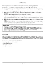
Protecting the electronic and/or electrical systems during charging and welding

To avoid damage to the electronic and/or electrical systems, always observe the following practices:

1. Never make or break any of the charging circuit connections when the engine is running, including the battery

connections.

2. Never short any of the charging components to ground.

3. Always disconnect the ground cable from the battery before arc welding on the machine or on any machine

attachment.

• Position the welder ground clamp as close to the welding area as possible.

• If you weld in close proximity to a computer module, then you should remove the module from the machine.

• Never allow welding cables to lie on, near, or across any electrical wiring or electronic component while you

weld.

4. Always disconnect the negative cable from the battery when charging the battery in the machine with a battery

charger.

NOTICE:

If you must weld on the unit, you must disconnect the battery ground cable from the machine battery.

The electronic monitoring system and charging system will be damaged if this is not done.

5. Remove the battery ground cable. Reconnect the cable when you complete welding.

WARNING

Battery acid causes burns. Batteries contain sulfuric acid.
Avoid contact with skin, eyes or clothing. Antidote (external): Flush with water. Antidote (eyes): flush
with water for 15 minutes and seek medical attention immediately. Antidote (internal): Drink large
quantities of water or milk. Do not induce vomiting. Seek medical attention immediately.
Failure to comply could result in death or serious injury.

W0111A

Special tools

The special tools that CASE CONSTRUCTION suggests and illustrate in this manual have been specifically re-
searched and designed for use with CASE CONSTRUCTION machines. The special tools are essential for reliable
repair operations. The special tools are accurately built and rigorously tested to offer efficient and long-lasting oper-
ation.

By using these tools, repair personnel will benefit from:

• Operating in optimal technical conditions

• Obtaining the best results

• Saving time and effort

• Working in safe conditions

51452136 23/07/2018

14

Summary of Contents for CX60C

Page 1: ...8114831 SERVICE MANUAL CX60C Mini Excavator Printed in U S A 2018 CNH Industrial Italia S p A All Rights Reserved Case is a trademark registered in the United States and many other countries owned or...

Page 2: ...SERVICE MANUAL CX60C Cab Tier IV final engine 51452136 23 07 2018 EN...

Page 3: ...uffler 10 10 10 501 Exhaust Gas Recirculation EGR exhaust treatment 10 11 10 400 Engine cooling system 10 12 10 414 Fan and drive 10 13 10 304 Engine lubrication system 10 14 Hydraulic systems 35 35 0...

Page 4: ...and track suspension 48 48 130 Track frame and driving wheels 48 1 48 100 Tracks 48 2 48 134 Track tension units 48 3 48 138 Track rollers 48 4 Cab climate control 50 50 100 Heating 50 1 50 200 Air c...

Page 5: ...ore information Please click here Then get the complete manual NOTE If there is no response to click on the link above please download the PDF document first and then click on it Have any questions pl...

Page 6: ...g 55 17 55 514 Cab lighting 55 18 55 408 Warning indicators alarms and instruments 55 19 55 DTC FAULT CODES 55 20 Booms dippers and buckets 84 84 910 Boom 84 1 84 912 Dipper arm 84 2 84 100 Bucket 84...

Page 7: ...INTRODUCTION 51452136 23 07 2018 1...

Page 8: ...Standard torque settings 10 Torque Special torque settings 12 Basic instructions Shop and assembly 13 Machine specifications 15 Weights 18 Dimensions 19 Conversion factors 21 Hydraulic contamination 3...

Page 9: ...arts and or components not approved by the manu facturer including those used for the servicing or repair of the product manufactured or marketed by the manufacturer In any case no warranty is given o...

Page 10: ...h or serious injury CAUTION indicates a hazardous situation that if not avoided could result in minor or moderate injury FAILURE TO FOLLOW DANGER WARNING AND CAUTION MESSAGES COULD RESULT IN DEATH OR...

Page 11: ...e inserted Gear Check that there is no wear and no damage Oil seal O ring gasket Always install new oil seals O rings and gaskets Apply grease to sections where oil seals and O rings will be inserted...

Page 12: ...sult in death or serious injury W1036A Lifting operation WARNING Crushing hazard The lifting systems must be operated by qualified personnel who are aware of the correct procedures to follow Make sure...

Page 13: ...Battery WARNING Battery acid causes burns Batteries contain sulfuric acid Avoid contact with skin eyes or clothing Antidote external Flush with water Antidote eyes flush with water for 15 minutes and...

Page 14: ...or per forming work on the hydraulic system Before applying pressure make sure all connections are tight and all components are in good condition Never use your hand to check for suspected leaks unde...

Page 15: ...w coolant mixtures to get into the soil Collect and dispose of coolant mixtures properly The air conditioning system contains gases that should not be released into the atmosphere Consult an air condi...

Page 16: ...m 5 90 8 90 lb ft M12 x 1 25 10 58 15 73 N m 7 80 11 60 lb ft 14 37 21 69 N m 10 60 16 00 lb ft M14 x 1 5 18 03 24 54 N m 13 30 18 10 lb ft 24 27 32 68 N m 17 90 24 10 lb ft M16 x 1 5 26 98 36 47 N m...

Page 17: ...9 mm 0 75 in 39 18 N m 28 90 lb ft 3 8 22 mm 0 87 in 49 08 N m 36 20 lb ft 1 2 27 mm 1 06 in 93 14 N m 68 70 lb ft 3 4 36 mm 1 42 in 176 26 N m 130 00 lb ft 1 41 mm 1 61 in 206 08 N m 152 00 lb ft 1 1...

Page 18: ...lt M16 2 0 246 8 336 2 N m 182 0 248 0 lb ft Swing bearing upper mounting bolt M16 2 0 262 1 320 9 N m 193 3 236 7 lb ft Swing bearing lower mounting bolt M16 2 0 262 1 320 9 N m 193 3 236 7 lb ft Pow...

Page 19: ...n tool Do not tap the seal with a hammer or mallet 6 While you insert the seal check that the seal is perpendicular to the seat When the seal settles make sure that the seal makes contact with the thr...

Page 20: ...ground cable from the machine battery The electronic monitoring system and charging system will be damaged if this is not done 5 Remove the battery ground cable Reconnect the cable when you complete w...

Page 21: ...PM Low idling speed 950 1050 RPM Rated fuel consumption 170 g Hp hr at 2400 RPM Starting motor 12 V 3 0 kW Alternator 12 V 100 A Battery 1 x 12 V x 100 A h Main pump Type Variable displacement axis pi...

Page 22: ...ratio 53 706 Cylinder Bore diameter x Rod diameter x Stroke 110 mm 4 3 in x 60 mm 2 4 in x 715 mm 28 1 in Boom cylinder Cushion Extend only Bore diameter x Rod diameter x Stroke 85 mm 3 3 in x 55 mm 2...

Reviews: