background image

8

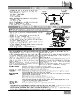
Step 12.

  Remove the two screws of the

switch housing cap.  Set the cap and screws
aside for use in Step 15.

REMOVE SWITCH HOUSING CAP SCREWS

Step 13.

  Install 2 of the 3 switch housing

screws onto the fan adapter plate, leaving

1

8

" threads visible.  Feed the wire connec-

tor from the fan through the center of the
switch housing.

Align the 2 screws on the adapter plate with
the keyhole slots of the switch housing.
Raise the switch housing, pulling on the fan
wire connector to assure no wires get
pinched.

Turn the switch housing counter clockwise,
engaging the 2 screws.  Install the third
screw and tighten all 3 screws.

INSTALL SWITCH HOUSING

SWITCH

HOUSING

2 SWITCH

HOUSING

SCREWS

SWITCH

HOUSING SCREW

Step 14.

  Plug the wire connector for the

fan into the wire connector for the switch
housing.  Assure that the clip from the fan
connector engages the notch on the switch
housing connector.

CONNECT WIRES

Step 15.

  If you are installing a light fix-

ture, please refer to the 

“3-Speed Optional

Light Fixture Installation”

 on the next page.

If no light fixture is being installed, care-
fully push the wires and components back
into the switch housing.  Align the guiding
pegs of the cap to the non-threaded holes
of the switch housing.  Reinstall the switch
housing cap screws removed in Step 12.

INSTALL SWITCH HOUSING CAP SCREWS

CLIP

NOTCH

U

TOPIAN

Summary of Contents for UTOPIAN

Page 1: ...cian should be consulted if you are unsure This fan is designed to be installed on an existing electrical outlet box The outlet box must be UL Listed for ceiling fan installations if it is not a new...

Page 2: ...s must be a minimum of 7 above the floor Do not locate the fan in a doorway or above a swinging door In any installation the tips of the blades must be at least 18 from the wall in order to provide su...

Page 3: ...turns Step C Securely tighten the set screw with the provided allen wrench to ensure safe operation of your fan Tip The downrod has a tapered thread that is designed to lock completely when correctly...

Page 4: ...sing the mount ing hardware provided with the outlet box ADDITIONAL HARDWARE 21 4 x 8 32 ROUNDED HEAD SCREW 2 FLAT WASHER 2 1 x 8 32 ROUNDED HEAD SCREW 2 CEILING WIRING CROSSBAR MOUNTING BRACKET FLAT...

Page 5: ...sbar mounting bracket with three of the 8 32 x 21 4 long canopy screws and canopy lock washers Using the screwdriver tighten the screw firmly by hand only UTOPIAN CANOPY SCREWS Step 4a Attach the fan...

Page 6: ...at the WHITE and BLACK wires are on opposite sides of the canopy and all wires are clear of the canopy opening Step 6 Install canopy hatch with the last canopy screw and lock washer To do this tilt th...

Page 7: ...only Step 9 Attach each blade to a blade holder securing it with the four blade screws provided Using the screwdriver tighten securely by hand only BLADE SCREW 4 PER BLADE BLADE BLADE HOLDER BLADE IN...

Page 8: ...Install the third screw and tighten all 3 screws INSTALL SWITCH HOUSING SWITCH HOUSING 2 SWITCH HOUSING SCREWS SWITCH HOUSING SCREW Step 14 Plug the wire connector for the fan into the wire connector...

Page 9: ...s controlled by the reverse pull chain on the side of the switch housing No changes in household wiring are required 1 Refer to light kit instructions to assemble and attach your light kit correctly 2...

Page 10: ...l Number 77xxD Dimensions A 10 7 B 12 22 C 3 D 11 2 E 5 6 Weight 25 lbs Motor 172mm x 20mm Direct Drive Blade Span With 50 Blade Pitch 16 No of Blades 5 Technology 3 Speed Airflow 6 152 cfm Electricit...

Reviews: