
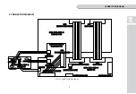
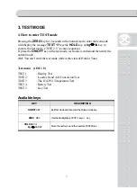
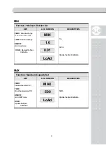
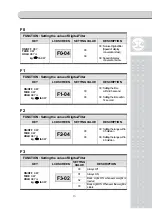
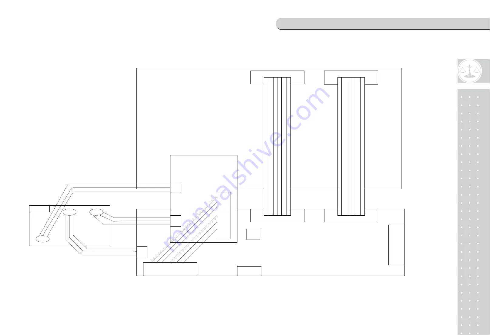
CONNECTOR DIAGRAM
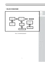
2. CONNECTOR DIAGRAM
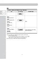
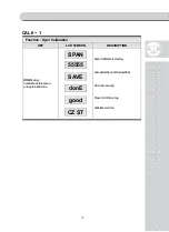
J1(CAL)
CN3(POWER&CHARGE)
CN7(DOWNLOAD)
CN5(LOADCELL)
CN4
ER)
CN6
(LCD DATA)
CN1
(LCD DATA)
6100-PNC-0909-0
MAIN PCB
(REMOCON&POW
CN2
(REMOCON&POWER)
6110-PNC-0909-0
DISPLAY PCB
6171-PC5-6170-0
CHARGER PCB
CN2
(BATTERY)
CN3
(POWER&CHARGE)
CN1
(ADAPTOR)
SW5
(DOWNLOAD S/W)
6151-PNC-0420-A
(CAL PCB)
BATTERY
CAL
ADAPTOR
CN1
(BATTERY)
FIG 2. CONNECTOR DIAGRAM.
6
Summary of Contents for NC-1
Page 1: ...2 ...
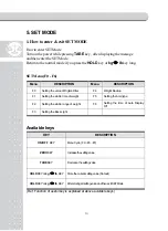
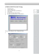
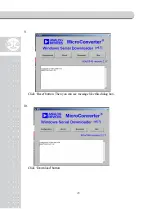
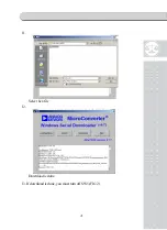
Page 20: ...21 11 Select hex file 12 Download is done 13 If download is done you must turn off SW5 FIG 2 ...
Page 24: ...4 Cal schematic SCHEMATIC DIAGRAM 25 ...
Page 25: ...26 8 PCB BOARD DIAGRAM 1 Main PCB board LED ...
Page 26: ...27 2 Display PCB board ...
Page 27: ...28 3 Charger PCB board ...
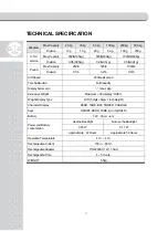
Page 28: ...29 9 DEVICE OF SPECIFICATION 1 MPU ADUC845 ...
Page 29: ...30 ...
Page 30: ...31 ...
Page 31: ...32 ...
Page 32: ...33 2 OPAMP OP2177 OP2277 ...
Page 33: ...34 ...
Page 34: ...35 ...
Page 35: ...36 3 REGULATOR LM2575 ...
Page 36: ...37 ...
Page 37: ...38 ...
Page 38: ...39 ...
Page 39: ...40 ...
Page 40: ...41 ...
Page 41: ...42 ...
Page 42: ...43 4 RESET TC1274 ...
Page 43: ...44 ...
Page 44: ...45 ...
Page 45: ...46 ...
Page 46: ...47 4 RESET TC1274 ...
Page 47: ...48 ...
Page 48: ...49 ...
Page 82: ...83 12 EXPLODE VIEW ...
Page 83: ...84 ...


