


3327 • P2 6/06
17
DC ELECTRICAL SYSTEM
SECTION 2
DC Electrical System
Your boat is equipped with a 12-volt DC (Direct Current) electrical system.
This is a comprehensive system that is designed to meet your present and future
12-volt electrical needs. Wire-runs and connections are positioned to prevent
abrasion and exposure to moisture, as well as to remain accessible for inspection,
repairs, and the addition of aftermarket electrical accessories.
Wires used throughout the DC electrical system are plastic-coated and color-
coded. Connections are made using crimped connector points. The electrical
system is virtually maintenance free, with only the batteries requiring periodic
inspection and maintenance.
Batteries
The DC electrical system is divided into three areas, each powered by one or
more 12-volt batteries:
• Engine Batteries
(2 batteries - one for each engine)
• Accessory Battery
• Generator Battery
Engine Batteries
Each propulsion engine has its own dedicated battery. These batteries are
located in the aft bilge: the port engine battery is directly beneath the port
cockpit hatch; the starboard engine battery is directly beneath the starboard
cockpit hatch.
Electricity from each battery to its engine is controlled by a master disconnect
switch. These switches are located in the engine room on a horizontal panel
on the aft centerline. To provide electricity to the engines, turn the master
disconnect switches to the “ON” position.
Refer to Section 9 - Hatches and/or Engine Room for the exact location of the
engine batteries and their master disconnect switches.
Accessory Battery
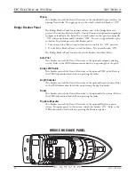
The equipment controlled by the three DC circuit breaker panels (Safety
Breaker Panel, DC Control Center and Bridge Breaker Panel) is powered by
a single battery. This battery is located in the aft bilge, directly beneath the
starboard cockpit hatch.
Electricity from the battery to the boat’s various DC circuit breaker panels
is controlled by a master disconnect switch. This switch is located on the
Safety Breaker Panel, which is located in a cabinet in the inboard end of the
galley counter. To provide electricity to these breaker panels, turn the master
disconnect switch to the “ON” position.
Refer to Section 9 - Hatches and Section 2 - Safety Breaker Panel for the exact
locations of the accessory battery and its master disconnect switch.
Summary of Contents for 380 SPORT
Page 1: ...HIN CDR _________________ 380 Sport Owner s Guide 2007 Version 1 ...
Page 2: ......
Page 4: ......
Page 6: ......
Page 8: ......
Page 28: ......
Page 40: ...28 3327 P2 6 06 DC ELECTRICAL SYSTEM SECTION 2 DC SCHEMATIC 3327 324 002 5 12 7 05 ...
Page 54: ...42 3327 P2 6 06 AC ELECTRICAL SYSTEMS SECTION 3 AC SCHEMATIC 3327 300 015 2 9 04 ...
Page 108: ......
Page 122: ......
Page 124: ...112 3327 P2 6 06 WARRANTY AND PARTS SECTION 9 Hatches ...
Page 129: ...3327 P2 6 06 117 WARRANTY AND PARTS SECTION 9 Bill of Material ...
Page 130: ......
Page 131: ...3327 P2 6 06 119 WARRANTY AND PARTS SECTION 9 Carver Limited Warranty ...