background image


I-855 

855 


Filtrate Pump 


855-15.04.EN 


moving  vane-type  meters  should  not  be 
grounded nor held during measurements. 


Do  NOT  use  test  equipment  known  to  be 
damaged or in poor condition. 

H.  NON-COMPLIANCE 

WITH 

SAFETY 

INSTRUCTIONS.


Non-compliance 

with 

safety 

instructions  may  result  in  personal  injury,  property 
damage,  or  unnecessary  damage  to  the  pumping  unit. 
Non-compliance  with  these  safety  instructions  will  also 
lead  to  forfeiture  of  any  and  all  rights  to  claims  for 
damages. Non-compliance, can for example, result in: 


Failure of important pumping unit functions. 


Failure of prescribed maintenance and servicing 
practices. 


Hazard  to  personnel  by  electrical,  mechanical, 
and chemical effects. 


Hazard  to  the  environment  due  to  leakage  of 
hazardous substances. 

Avoid  Possible  Non-Compliance.

    The  following 

specific safety precautions apply to the pumping unit: 


Do  NOT  exceed  maximum  discharge  pressure 
on discharge case (100 psig/ 690 kpa). 


Do  NOT  operate  pump  without  fluid  to  seal  or 
packing. 


Do  NOT  run  pump  dry  for  extended  periods  of 
time (longer than 1/2 hour) 


Do  NOT  run  pump  against  a  closed  discharge 
valve. 


Do  NOT  exceed  the  Maximum  rated  speed 
(2400 rpm). 


A  check  valve  should  be  installed  in  the 
discharge line. 


Pumps  assembled  by  Carver  without  a  motor 
will have  a Declaration  of Incorporation  and  will 
not have a CE mark. When a motor is added, all 
guards must be installed, the motor must be CE 
marked  and  the  completed  machine  reviewed 
for  compliance  for  applicable  EHSRs  before  a 
CE mark is attached. 

III.  EQUIPMENT DESCRIPTION. 

A.  PUMP HISTORY. 

The  Filtrate  Pump  line  was  desig

ned in the late  1950’s 

at  the  request  of  a  large  Original  Equipment 
Manufacturer  (OEM)  of  vacuum  filtration  equipment.  
The  company  had  found  that  the  typical  centrifugal 
pump  would  not  operate  against  the  high  vacuum  in  a 
filtrate  receiver  tank  without  the  inclusion  of  a 
hydrostatic  leg  in  order  to  provide  enough  Net  Positive 
Suction  Head  Available  (NPSHA)  to  prevent  the  pump 
from cavitating and destroying itself. 

The  receiver  tank  flange-mounted  Filtrate  Pump  was 
designed  to  solve  the  OEM's  problem  and  they  have 
been used in pumping liquids under vacuum or with very 
low suction pressures ever since.  

B.  PUMP FEATURES. 

The Filtrate Pumps do not require a hydrostatic leg, will 
operate against vacuums up to 660 mm Hg (

26” Hg) on 

the  suction  side  and  if,  on  occasion,  it  pumps  the 
receiver tank dry, or the inflow of process liquid into the 
tank  is  interrupted,  it  will  continue  to  run,  will  maintain 
the  vacuum  in  the  system,  and  when  the  suction  again 
becomes flooded it will prime itself and resume pumping 
the  process  liquid. 

An  important  aspect  of  the  pump’s 

operation  is  that  it  accomplishes  all  of  the  foregoing 

without

  the  use  of  mechanical  or  electrical  level 

controls  on  the  receiver  tank,  thereby  simplifying  and 
enhancing the reliability of the entire system. 
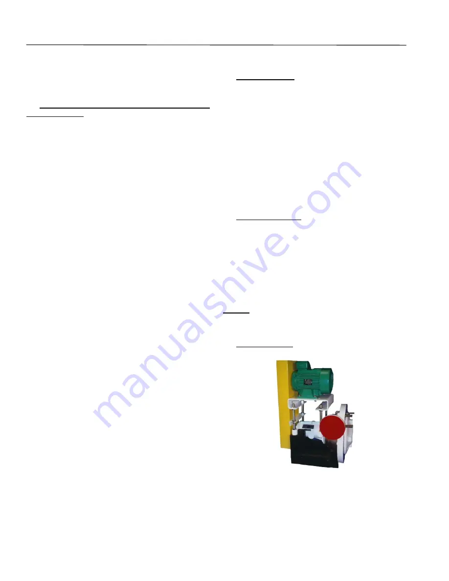
C.  PUMP DETAILS. 


Figure 1.  Model 855-OH Pump 

The  line  has  two  variations.  The  standard  is  the  flange 
mounted  Model  855-OH  which  features  an  overhead  v-
belt drive  arrangement for varying the  pump speed and 

Summary of Contents for 855 Series

Page 1: ...____________________ Serial Numbers _____________________________________ These operating instructions contain fundamental information and precautionary notes Please read the manual thoroughly prior to installation of unit electrical connection and commissioning It is imperative to comply with all other operating instructions referring to components of individual units I 855 855 15 04 EN ATEX REV ...

Page 2: ... Declaration of Conformity of Completed Machinery valid for 855 pumps supplied complete with a motor The product described in this Declaration of Conformity complies with the Applicable European Directives EHSRs and relevant sections of the Applicable International Standards Motors for CE marked pumps will have motors that are marked to confirm that they comply with the Low Voltage Directive 2006 ...

Page 3: ...______________ Specific Gravity _______________________________ Viscosity ______________________________________ Service ______________________________________ PUMP MATERIALS Casing _________________________ Impeller _______________________ Shaft _______________________ Gaskets _____________________________________ Bearing Frame _________________________________ Mechanical Seal Packing ___________...

Page 4: ...I 855 855 Filtrate Pump 855 15 04 EN NOTES ON INSPECTION AND REPAIRS INSPECTION DATE REPAIR TIME REPAIRS COST REMARKS ...

Page 5: ...Positive Suction Head NPSH 5 B Changing Pump Speed 6 C Effects of Viscosity 6 D Effects of Specific Gravity 6 V TECHNICAL DATA 6 VI INSPECTION AND STORAGE 9 A Inspection 9 B Packing for Return 9 C Storage of Pump 9 SECTION PARAGRAPH PAGE VII INSTALLATION 10 A Location 10 B Handling 10 C Pre Installation Procedures 11 D Piping 11 E Auxiliary Piping Connections and Gauges 11 F Motor 11 G Direction o...

Page 6: ...g out 5 3 Stuffing Box Dimensions 7 4 Transport of the Bare Pump 10 5 Transport of Close Coupled Pump 10 6 Transport of Complete Unit 10 7 Removing Packing with Hook 22 8 Packing Alignment 23 9 Mechanical Seal 23 10 Belt Tensioning 25 11 Swing out Assembly 26 12 Drilling Tank Flange for Swing out 27 13 Adjuster Bolt Closed position 27 14 Adjuster Bolt Open position 27 15 Sectional Assembly Close C...

Page 7: ...ating to safety instructions have been met B MACHINERY DIRECTIVE 2006 42 EC This product is designed to Conform with Machinery Directive 2006 42 EC Safety of Machinery EN ISO 12100 2010 EN ISO 13732 1 2008 EN 626 1 2008 EN ISO 13857 2008 and the EHSRs Complete Machinery for use in EU and EAA will have CE mark and Declaration of Conformity Motors for CE marked pumps will have motors that are marked...

Page 8: ... safety The use of other parts can invalidate any liability of Carver Pump for consequential damage and or warranty I UNAUTHORIZED MODES OF OPERATION The warranty relating to operating reliability and safety of the unit supplied is only valid if the pumping unit is used in accordance with its designated use as described in the following sections The limits stated on the nameplate must not be excee...

Page 9: ... manual and pumping unit The pumping unit must have cooled down to ambient temperature pump pressure must have been released and the pump must have been drained before working on any pumping unit Work on the pumping unit must be carried out during shutdown The shutdown procedure described in the manual for taking the unit out of service must be adhered to Pumps handling fluids that are hazardous t...

Page 10: ...ine reviewed for compliance for applicable EHSRs before a CE mark is attached III EQUIPMENT DESCRIPTION A PUMP HISTORY The Filtrate Pump line was designed in the late 1950 s at the request of a large Original Equipment Manufacturer OEM of vacuum filtration equipment The company had found that the typical centrifugal pump would not operate against the high vacuum in a filtrate receiver tank without...

Page 11: ... to carry the loads from the liquid end of the pump to the base and to transport power from the motor 200 to the impeller 3 The bearing frame has an outboard ball bearing 16 and an inboard ball bearing 18 This bearing frame is designed to be belt driven by an overhead OH mounted motor Item 23 Motor Plate An adjustable motor plate is designed to provide adequate support for the pump and motor 200 s...

Page 12: ...tal head will be affected by a change in the specific gravity of the liquid pumped However since the discharge pressure in Pounds per Square Inch PSI and the brake horsepower required driving the pump are functions of the specific gravity of the liquid both will be affected in direct proportion by any change in specific gravity Therefore an increase in specific gravity will raise the discharge pre...

Page 13: ... 5 61 5 58 5 52 52 2 2 63 5 60 5 53 53 3 0 65 5 62 5 55 55 4 0 67 64 57 57 5 5 68 5 65 5 57 5 57 5 7 5 70 67 58 5 58 5 11 0 72 69 60 5 60 5 15 0 73 70 61 5 61 5 18 5 73 5 70 5 62 5 62 5 22 0 74 71 63 5 63 5 Measured at a distance of 1 m from the pump outline Room and foundation influences have not been included The tolerance for these factors is 1 to 2 dB Figure 3 Stuffing Box Dimensions ...

Page 14: ...C Max power BHP 2400 RPM 20 30 33 Maximum Speed RPM 2400 2400 2400 Pump Size s 1 1 1 2 2 2 1 2 3 4 Maximum Discharge Pressure 100 psig 690 kPa Bearing type radial bearing 6307 5307 5308 thrust bearing 6307 5307 5308 Lubrication method standard Sealed for life Grease L10 bearing life hrs radial 50 000 50 000 50 000 thrust 100 000 100 000 100 000 Radial to thrust bearing C L in 5 83 5 83 5 83 Shaft ...

Page 15: ...ould be prepared for storage according to the motor manufacturer s instructions in the motor manufacturer s maintenance manual which should come with the motor CAUTION A pump which is made of iron or steel that sits in extreme heat high humidity or full or partially full water over 30 days will rust and will most likely seize If the pump rusts and or seizes a complete overhaul and repair may be ne...

Page 16: ...Net Positive Suction Head Required NPSHR by the pump B HANDLING CAUTION Use a hoist with adequate lifting capacity See pump nameplate for weights Do not pick up the complete unit by the motor or the pump shafts or motor lifting eyes If the pumping unit slips out of the sling arrangement it may cause injury to personnel and or damage to the pumping unit Moving the unit requires proper preparation a...

Page 17: ...ck valve to isolate the pump Horizontal discharge lines should be installed with a continuous upward slope away from the pump Refer to Figure 19 for the discharge flange dimensions CAUTION All piping connections must be made with the pipe in a freely supported state Do not apply vertical or side pressure to align the piping with the pump flange Before connecting the suction discharge and auxiliary...

Page 18: ...If excessive vibration or noise continues consult a Carver representative B PRIMING Dry running a centrifugal pump can result in extensive damage and possible seizing It is therefore imperative that the pump be primed prior to initial start up and that prime must be maintained through subsequent start stop cycles Follow the procedure listed below 1 Check the level in the tank to see that the pump ...

Page 19: ...azardous fluid extreme care must be taken to ensure safety of personnel when attempting to drain pump Suitable protection devices should be used and or protective clothing should be worn 1 Stop the pumping unit in accordance with the directions on the electrical power supply 2 Tagout and lockout power to motor according to OSHA Standard 1910 147 3 Close discharge and suction valves and any auxilia...

Page 20: ...or plugged discharge line 1 Open valves and if necessary lock valves open to prevent accidental closure 2 Inspect and clean discharge 4 Clogged impeller 1 Disassemble pump and clean impeller if necessary 5 Reverse rotation 1 Direction of rotation for 855OH pumps is clockwise as viewed from belt end of pump shaft Direction of rotation for 855CC pumps is clockwise as viewed from fan end of motor 6 M...

Page 21: ... or more of the following measures can be taken a Partially close discharge valve reducing pump capacity to a point where driver is not overloaded b Install more powerful driver Consult Carver Pump Company specifying exact operating conditions Pump overloads motor 1 Stop the pump refer to Section VIII Paragraph E 1 Speed too high 1 Check pumps RPM and determine correct sheave and belts for proper ...

Page 22: ...k belt condition and alignments Semi annual Inspection If stand by pumps are installed it is advisable to operate pumps on a rotational system to give each pump a periodic duty This ensures that stand by pumps will have periodic operation and always be in good condition for instant start up 12 500 Hours Overhaul For pump overhaul complete Section XI Service and Repair A LUBRICATION OF PUMP BEARING...

Page 23: ... location of parts followed by an item number Prepare the pumping unit for disassembly using the following list 1 Read this entire section and study the applicable sectional view drawing and parts list before disassembling the pump 2 Stop the pumping unit refer to Section VIII Paragraph E NOTE Refer to cartridge seal 90 refer to vendor instructions for proper mechanical seal removal procedure 3 Fo...

Page 24: ... with are options or vary by pump After completion of dismantling all parts should be thoroughly cleaned or replaced by new ones if necessary All gaskets and sealing faces should be perfectly clean When cutting new gaskets make sure they are exactly the same thickness as the old ones unless noted CAUTION Use a hoist with adequate lifting capacity refer to Section VII Paragraph B for lifting the co...

Page 25: ...place with new 15 If desired pull ball bearing 18 from shaft 6 16 If desired pull ball bearing 16 from shaft 6 C PARTS INSPECTION 1 All parts should be thoroughly cleaned with a suitable solvent or replaced with new ones if necessary 2 All sealing faces should be perfectly clean All ball bearings mechanical seals gaskets O rings lip seals and locking devices with a nylock feature are to be replace...

Page 26: ...by pump For close coupled units start with step 6 1 If removed install ball bearings 16 and or 18 onto shaft 6 CAUTION Handle lip seal 169 with care Mishandling could damage faces of the lip seal 2 Install the lip seals 169 in the bearing caps 35 3 Install the shaft 6 in the bearing frame 19 4 Install one paper gasket 73 on the impeller end bearing cap 35 Install impeller end bearing cap on bearin...

Page 27: ...the gauge in a full circle to check the impeller clearance a Impeller clearance should be 015 to 020 b If the impeller 3 needs shimmed towards the suction cover 10 remove the suction cover and impeller and add impeller shims 15 behind the impeller as required to obtain the correct clearance c If the suction cover needs shimmed remove the suction cover and add additional gaskets 73A to obtain the c...

Page 28: ...ines and auxiliary connections as necessary 37 Confirm water is turned on to external flush lines for pumps equipped with water cooling for either the packing or the mechanical seal 38 Remove all tags from valves and switches 39 Start pumping unit in accordance with Section VIII Paragraph C E REPLACEMENT OF PACKING Pumps equipped with packing have a lantern ring which is located in line with the f...

Page 29: ...and 17 follower should be at least 6mm 1 4 to allow future gland adjustments 20 Rotate shaft 6 by hand to ensure shaft is not binding 21 Allow liberal leakage at start up 22 Slowly adjust leakage to an acceptable level by tightening gland hex nuts 615 slowly and evenly Final adjustments should be made by rotating gland hex nuts one flat at a time NOTE If stuffing box is hot to the touch approximat...

Page 30: ...n their life Loose belts cause slippage and excessive wear as well as poor performance G 1 General Belt driven pump sets must always be earthed electrically grounded The condition of the belts must be checked regularly After fastening the unit to the tank flange and connecting the piping the belt drive must be thoroughly checked and the belts re tensioned if required CAUTION Reinstall and tighten ...

Page 31: ... will result in a reduced service life Additionally high tension creates an unnecessarily high load on the bearings of the shaft 3 The belts 276 must be fitted by hand without using force For this purpose reduce the distance between the sheaves 277 by moving the motor plate 23 downwards Pulling the belts under tension over the edges of the sheaves or using metal tools can cause invisible damage to...

Page 32: ...l bolt through the swing out arm located approximately 7 30 10 30 o clock positions 4 Place adjuster bolts 54B in top and bottom positions of lower hinge plate 53A 5 Assemble hinge plates lower and upper 53A and 53B by inserting swing out hinge bolt 608 through upper hinge plate 53B adjuster bolts 54B and lower hinge plate 53A Secure with adjuster bolt snap ring 176 and swing out hinge hex nut 619...

Page 33: ... the manufacturer s instructions J CHECK VALVE If applicable the check valve should be maintained in accordance with the manufacturer s instructions XII PARTS LISTS AND DRAWINGS This section contains listings of parts and corresponding drawings Table 9 notes the recommended spare parts for this pumping unit Refer to Figures 15 16 and 17 for the location of parts identified by item numbers Template...

Page 34: ...605 Screw Guard Cover 46X Key Motor Bushing 606 Screw Splash Guard 53A Hinge Plate Lower 607 Screw Slide Guard 53B Hinge Plate Upper 608 Bolt Swing out Hinge 54A Spacer Plate 615 Hex Nut Gland 54B Adjuster Bolt 616 Jam Nut Adjustment 54C Adjuster Wrench 617 Hex Nut Guard 63 Retaining Ring Packing 618 Hex Nut Motor 63A Throttle Bushing Seal 619 Hex Nut Swing out Hinge 68 Spacer Mechanical Seal 620 ...

Page 35: ...ump Bushing 14 Shaft Sleeve 68 Spacer Mechanical Seal 15 Impeller Shim set 73 Gasket Frame Cap set 16 Ball Bearing 73A Gasket Casing Suction 17 Gland 73B Gasket Suction Tank 18 Ball Bearing Impeller End 89 O Ring Sleeve 28 Impeller Washer 90 Mechanical Seal 29 Lantern Ring 180 Packing 32 Key Impeller Parts are options that vary by pumping unit ...

Page 36: ...I 855 855 Filtrate Pump 855 15 04 EN 30 Figure 15 Sectional Assembly Close Coupled Pump Shown with Mechanical Seal ...

Page 37: ...I 855 855 Filtrate Pump 855 15 04 EN 31 Figure 16 Sectional Assembly with Overhead Drive Shown with Packing ...

Page 38: ...I 855 855 Filtrate Pump 855 15 04 EN 32 Figure 17 Optional Swing out Assembly ...

Page 39: ...I 855 855 Filtrate Pump 855 15 04 EN 33 Figure 18 Model 855 Tank Mounting Flange ...

Page 40: ...I 855 855 Filtrate Pump 855 15 04 EN 34 Figure 19 Model 855 Universal Discharge Flange ...

Page 41: ...I 855 855 Filtrate Pump 855 15 04 EN This page intentionally left blank ...

Page 42: ...2415 Park Avenue Muscatine IA 52761 Phone 563 263 3410 www carverpump com 855 Filtrate Pump IOM 855 15 04 EN ATEX REV 0 ...

Reviews: