G
33
CARSON X8E Chassis 500409015 / 500409016
Technical Data Motor and ESC
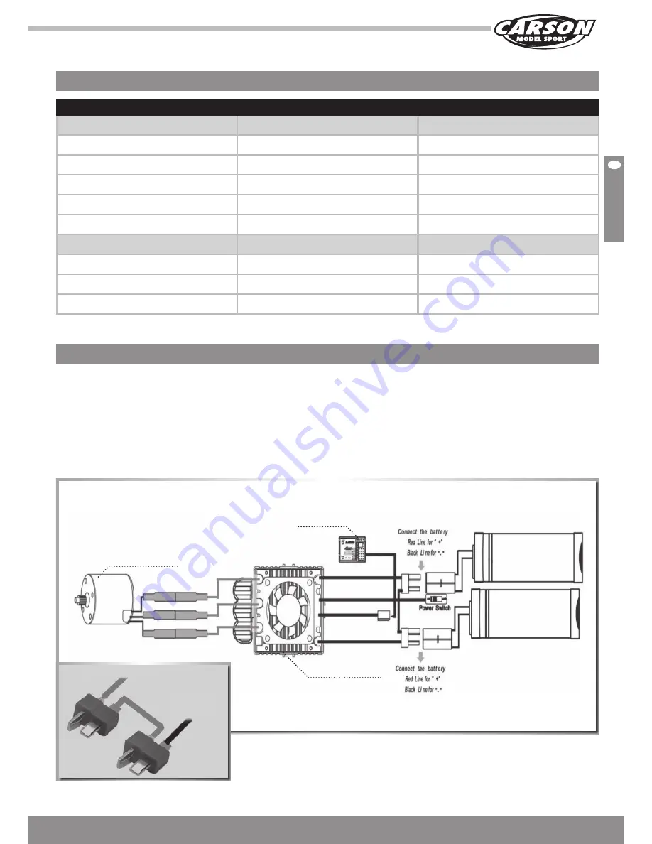
Connect the ESC, motor, receiver, battery and
servo according to the following diagram.
Positive (+) and negative (-) wires of the ESC are connected with the
battery pack.
A, B and C are connected with the motor wires. The control cable of
the ESC (wires in black, red and white colour) is connected with the
throttle channel of the receiver (usually CH2).
The A, B, C wires of the ESC can be connected with the motor wires
freely (without any order).
If the motor runs in the opposite direction, please swap any two wire
connections.
4S – Connection/Cabling
7,4 V
Lipo
7,4 V
Lipo
dragsTer 4s
dragsTer 6s
Brushless Motor:
Motor
Sensorless
Sensorless
U/min
1980 UpV
2000 UpV
U/min @ 14,8 V
29.304
44.400
Short term
80 A
120 A
Dimensions (A- Ø x L)
36 mm Ø x 66 mm L
40 mm Ø x 74 mm L
Brushless esC:
Forward
yes
yes
Reverse
yes
yes
Input voltage
2-4 LiPo-cells
2-6 LiPo-cells
Speedcontroller
Motor
Red wire to the positive of the ESC
Black wire to the
negative of the ESC
Receiver


