background image

14

GB

CARSON X10NB Chassis

Contents

Preface ..........................................................................................................................13

Included Items ...........................................................................................................14

Safety Precautions ....................................................................................................15

Additional Items Needed for Starting the Engine ........................................16

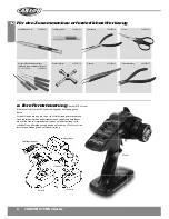
Tools Needed for the Assembly...........................................................................17

a.  Your Radio System .............................................................................................17

b. Chassis ....................................................................................................................18

c.   Plug in Receiver Batteries ................................................................................18

d. Check 1...2...3 

........................................................................................................19

e. Final Preparations... 

............................................................................................19

f. Showtime... 

almost! 

...........................................................................................20

g.  Turn the Power Switch on ...............................................................................21

h.  How to Control your Model ............................................................................21

i.  Care and Maintenance .....................................................................................22

j. Troubleshooting 

.................................................................................................23

Assembly  ....................................................................................................................24

Spare Parts ..................................................................................................................48

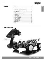
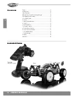
Included Items

Transmitter
(only for RTR version)

cluded Items

mitter

for RTR version)

0NB Chassis

Chassis

Summary of Contents for X-10NB Chassis

Page 1: ...CARSON X10NB Chassis 쮕 Betriebsanleitung Seite 2 12 Instruction Manual Page 13 23 X 10NB Chassis ...

Page 2: ...araturen oder gelieferte Ersatzteile werden in Rechnung gestellt Von der Garantie ausgeschlossen sind Beschädigung oder Ausfall durch Nichtbeachten der Sicherheitsan weisungen oder der Bedienungsanleitung höhere Gewalt Unfall fehlerhafte oder außergewöhnliche Beanspruchung fehlerhafte Handhabung eigenmächtige Veränderungen Blitzschlag oder anderer Einfluss von Hochspannung oder Strom Schäden die d...

Page 3: ...rforderliches Zubehör 5 Für den Zusammenbau erforderliches Werkzeug 6 a Ihre Fernsteuerung 6 b Chassis 7 c Einlegen der Empfängerbatterien 7 d Funktionstest 8 e Letzte Vorbereitungen 8 f Es kann losgehen fast 9 g Einschalten der RC Anlage 10 h Steuern des Modells 10 i Wartung und Pflege 11 j Problembehandlung 12 Montageanleitung 24 Ersatzteile 48 3 CARSON X10NB Chassis Chassis ...

Page 4: ......

Page 5: ...und wechseln Sie defekte oder abgenutzte Bauteile gegen Original Ersatzteile aus Wir wünschen Ihnen viel Spaß mit Ihrem CARSON Modellauto und jederzeit gute Fahrt Zum Betreiben des Motors erforderliches Zubehör Für den Sender werden 4 Stück AA Batterien Akkus benötigt NO Bezeichnung Motorart Kraftstoffart Temperatur 500905006 Glühkerze Rossi R2 heiß 2 3 5 ccm ohne Nitro 0 15C 500905007 Glühkerze R...

Page 6: ...sen Sie die Ihrem RC System beiliegende Anleitung genau durch Vor dem Einbau müssen die Servos in Mittelstellung gebracht werden Dazu schalten Sie bitte den betriebsbereiten Sender und Empfänger ein Stellen Sie die Trimmhebel am Sender auf Mittelstellung Jetzt schalten Sie den Empfänger und dann den Sender aus Die Servos sind jetzt für den Einbau genau auf Neutralstellung Empfängerantenne Empfänge...

Page 7: ...is c Einlegen des Empfängerakkus Achten Sie auf die korrekte Polung Verbinden Sie dann den Akku mit dem zugehörigen Stecker zum Empfänger Schwarz muss mit schwarz und rot mit rot verbunden werden Schließen Sie dann das Batteriefach mit der zugehörigen Abdeckung Insider Tipp Benutzen Sie wiederaufladbare Akkus Verwenden Sie unseren NiMh 6 V 1100 mAh Akkupack No 500608104 Bild 1 ...

Page 8: ... Benutzen Sie den TH Trimm siehe Bild 3 um den Servoarm wenn nötig in die neutrale Position zu bringen In der Neutralposition sollten die Bremsen nicht schleifen Die Einstellung erfolgt mit einem 1 5 mm Inbusschlüssel über einen Stellring am Bremsgestänge Wenn Sie mit den Einstellungen zufrieden sind bringen Sie den Luftfilter wieder an d Funktionstest e Letzte Vorbereitungen Stecken Sie die Kraft...

Page 9: ...nfahrt Nicht verbranntes Öl des Kraftstoffes kann sich am Auspuff sammeln legen Sie etwas unter Lassen Sie das Auto im Leerlauf über 2 bis 3 Tankfüllungen laufen und überprüfen Sie die Temperatur des Motors etwa alle zwei Minuten Lassen Sie zwischen den Tankfüllungen 10 15 Min Pause zum Abkühlen Der Motorkühlkörper sollte mit dem Finger berührt werden können und nicht zu heiß sein ACHTUNG Nicht an...

Page 10: ...errad bis zum Anschlag nach rechts und links Die Räder sollen dem Lenkausschlag folgen Schlagen die Räder entgegengesetzt ein betätigen sie den Servo Reverse Schalter ST in Position REV Zum Regeln der Fahrgeschwindigkeit betätigen Sie den Gas Bremshebel nach hinten Vorwärtsfahrt Gas geben bzw nach vorne Bremsen Rückwärtsfahrt g Einschalten der RC Anlage Ziehen Sie die Senderantenne ganz heraus Bei...

Page 11: ... haben eine sehr lange Lebensdauer und bei richtiger Wartung und Tuning können Sie das Modell stundenlang ohne Unterbrechung fahren Ausschalten Nach Beendigung des Fahrens gibt es zwei Möglichkeiten den Motor auszuschalten Die erste Möglichkeit ist ein Tuch dicht auf das Aus puffrohr zu drücken Der Motor muss im Leerlauf sein vorzugsweise sollten die Bremsen betätigt sein Die zweite Möglichkeit be...

Page 12: ... geradeaus Lenkungstrim ist nicht korrekt eingestellt Radmuttern sind lose Modell bleibt nicht stehen Trimmung für den Gas Bremshebel ist nicht korrekt eingestellt Modell fährt zu langsam Motor hat an Leistung verloren Die hinteren Radmuttern sind lose Staub Fremdkörper ist in das Getriebe gelangt Kontrollverlust Störungen j Problembehandlung Lesen Sie dies schon bevor es passiert Der Motor spring...

Page 13: ...for repair or replacement of the product made after the expiration of the warranty period The Warranty does not cover Damage or failure caused by or attributable to acts of God abuse accident misuse improper or abnormal usage failure to follow instructions improper installation or maintenance alteration lightning or other incidence of excess voltage or current Damage caused by losing control of yo...

Page 14: ...7 a Your Radio System 17 b Chassis 18 c Plug in Receiver Batteries 18 d Check 1 2 3 19 e Final Preparations 19 f Showtime almost 20 g Turn the Power Switch on 21 h How to Control your Model 21 i Care and Maintenance 22 j Troubleshooting 23 Assembly 24 Spare Parts 48 Included Items Transmitter only for RTR version cluded Items mitter for RTR version 0NB Chassis Chassis ...

Page 15: ...of the model is not waterproof Therefore do not drive while it s raining snowing or in puddles or wet grass Always avoid running radio control models in restricted confined or populated areas Keep away from roads highways people and animals Do not drive if you are overtired or your reactivity is impaired in another way Watch your model constantly and do not become distracted The body shell should ...

Page 16: ... single loose screw can result in a dangerous situation for your model Maintain your model regularly and replace damaged or worn out parts by genuine spare parts We wish you great fun with your CARSON model car NO Article Motor Fuel Temperature 500905006 Glow plug Rossi R2 hot 2 3 5 ccm without Nitro 0 15C 500905007 Glow plug Rossi R3 medium 3 5 6 ccm without Nitro 2 18C 500905008 Glow plug Rossi ...

Page 17: ...ead the instructions provided with your radio system before using it The servos must be set at the centre position before installation To set the servos at a neutral position turn on the transmitter and receiver Set the trim levers in the centre position and turn off the receiver and then the transmitter The servos will be in proper neutral position for installation Receiver antenna Batteries for ...

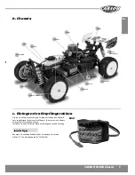
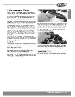
Page 18: ...into the switch harness inside the radio case Black goes to black and red goes to red Replace the radio case cover Racer Tip Use rechargeable batteries Use our NiMh 6 V 1100 mAh battery pack 500608104 Fuel tank Motor Air filter Muffler Front tyre Rear shock unit Rear tyre Receiver box Throttle servo Steering servo Front shock unit Chassis Picture 1 Wing ...

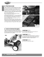
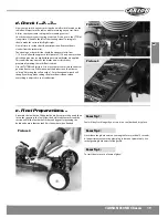
Page 19: ...to drive Use the TH TRIM tab picture 3 to move the servo arm into the neutral position if necessary While in neutral the brakes should not be set to drag Adjusting the collars with a 1 5 mm hexagonal wrench will change your drag brake settings Replace the air cleaner when everything is adjusted to your satisfaction e Final Preparations Assemble the fuel bottle Fill the fuel bottle by compressing i...

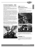
Page 20: ...e exhaust so be prepared Let the car idle like this for 2 3 tanks of fuel checking the engine temperature every 2 minutes Please allow a break of 10 15 in between filling the tank to allow the engine to cool down You should be able to touch the head of the engine with your fingertips and it will be hot but not uncomfortably so Attention Do not touch If it seems very hot richen turn counter clockwi...

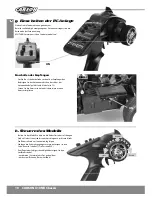
Page 21: ...iving speed actuate the throttle brake backwards forward driving accelerating or forwards braking reversing Switch on the receiver Power switch is on the radio box Fix the receiver antenna and wire see page 73 Put the body on and fix it with the body split pins h How to Control Your Model g Turn the Power Switch on Pull the transmitter antenna out completely The range of the remote control is redu...

Page 22: ... time and with proper maintance and tuning you can drive the model for hours at a time After Use When you have finished running your car there are two options to shut the engine down The first method is to place your thumb over the exhaust outlet Wear gloves Make sure your engine is normal idle preferable with the brake activated The second method is to pinch off the air supply from the engine Do ...

Page 23: ... run straight Steering trim is not adjusted correctly Front and rear wheel nuts are too loose Doesn t stop Throttle trim is not adjusted correctly Running too slowly Motor has lost power Rear wheel nuts are too loose Dust or foreign objects are inside gears Hard to control glitching j Troubleshooting Please read this in the event of a problem Engine won t start Engine flooded Too much fuel in engi...

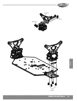
Page 24: ...Montage CARSON X10NB Chassis 1 Chassis Chassis 500405351 500105304 500105302 500105303 500105303 3 x 3 mm 3 x 10 mm 500405351 500405351 M3 3 x 10 mm 500105304 500105304 3 x 10 mm Montageanleitung Assembly ...

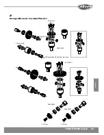
Page 25: ... Montage CARSON X10NB Chassis 2 Montage Differential Assembly differential 2 5mm E clip 2 5 mm E clip 2 5 x 8 mm 500405362 500405362 3 x 8 mm 3 x 8 mm 500405362 500105301 Diff complete Front Rear are same ...

Page 26: ...ARSON X10NB Chassis 3 Getriebe vorne Gear front 4 Getriebe hinten Gear rear 500405353 500405353 500405362 500405362 500105304 500105304 3 x 8 mm 3 x 16 mm 3 x 16 mm 500405353 500405353 3 x 16 mm 3 x 16 mm 3 x 8 mm ...

Page 27: ...27 Montage CARSON X10NB Chassis 500105304 3 x 12 mm 500105304 3 x 10 mm ...

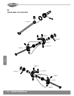
Page 28: ...28 Montage CARSON X10NB Chassis 5 Antriebswellen Front Drive Shaft 500405446 500405354 500405445 500405445 500405354 500405354 500405446 500405357 500405354 500405354 500405354 500405354 500405357 ...

Page 29: ...29 Montage CARSON X10NB Chassis 5 Vorderachse Assembly Front end 500405445 500405352 500405352 500405357 500405447 500405350 500405350 500405351 500405351 500405350 500105302 ...

Page 30: ...30 Montage CARSON X10NB Chassis 500405347 ...

Page 31: ...31 Montage CARSON X10NB Chassis 6 Hinterachse Assembly Back end 500405354 500405354 500405350 500405350 500405350 500405351 500405351 500405351 500405351 500405351 3 x 8 mm ...

Page 32: ...32 Montage CARSON X10NB Chassis 500405347 500405347 500405447 ...

Page 33: ...33 Montage CARSON X10NB Chassis 7 Stabilisator Anti Rollbar 500105305 3 x 10 mm 500405345 500405345 500405345 3 x 3 mm 3 x 3 mm 3 x 3 mm 3 x 3 mm 500405345 500405345 500405345 3 x 8 mm 3 x 8 mm ...

Page 34: ...34 Montage CARSON X10NB Chassis 8 Mitteldiferenzial Center differential 500105306 500105307 500105308 3 x 16 mm 3 x 10 mm 3 x 16 mm 500105309 500105311 500105310 ...

Page 35: ...35 Montage CARSON X10NB Chassis 9 Servosaver Servo Saver 500405360 500405360 500405360 3 x 10 mm 3 x 10 mm ...

Page 36: ...36 Montage CARSON X10NB Chassis 10 Oberdeck Upperdeck 500105304 500105305 500105309 500405347 500405347 3 x 10 mm 3 x 18 mm ...

Page 37: ...37 Montage CARSON X10NB Chassis 1 1 Chassisversteifung Chassis brace 500105305 500105309 3 x 10 mm 3 x 10 mm ...

Page 38: ...38 Montage CARSON X10NB Chassis 12 RC box RC Box 500105312 500105312 500105312 500105312 3 x 10 mm 3 x 10 mm ...

Page 39: ...39 Montage CARSON X10NB Chassis 13 Servos Servos 500105305 500105305 500405347 3 x 8 mm 3 x 8 mm 3 x 10 mm ...

Page 40: ...40 Montage CARSON X10NB Chassis 14 Tank Fuel tank 15 Motor Kupplung Motor Kupplung Pipe 500105313 500105314 Fuel tank 3 x10 mm 3 x12 mm 3 x 25 mm ...

Page 41: ...41 Montage CARSON X10NB Chassis 16 Luftfilter Air Cleaner 3 x 8 mm 3 x 8 mm 500105315 500105315 ...

Page 42: ...42 Montage CARSON X10NB Chassis 17 Gas Bremsgestänge Throttle Brake Linkage 500105316 3 x 10 mm 3 x 10 mm ...

Page 43: ...43 Montage CARSON X10NB Chassis 18 Stoßdämpfer Shocks 500405342 500405342 Oil 500405342 M3 3 x 16 mm ...

Page 44: ...44 Montage CARSON X10NB Chassis 19 Spoiler Wing 500405342 500800080 500800080 500800080 500405342 M3 3 x 20 mm 3 x 8 mm ...

Page 45: ...45 Montage CARSON X10NB Chassis 20 Räder Wheels Rear Front 500900099 M4 500405445 ...

Page 46: ...Montage 46 CARSON X10NB Chassis 21 Karosserie Body 500800080 500800080 ...

Page 47: ...47 CARSON X10NB Chassis Notizen ...

Page 48: ...et Halter v h Suspension arm holder f r 500405357 Kugellager Set Ball bearing set 500405345 Stabilisator Set vorne hinten Sway bar set front rear 500405352 2x Achsschenkel Set hinten 2x Rear hub set 500405360 Servosaver Lenkeinheit Servosaver steering set 500405362 Di ial vorne komplett Di mplete front 500405353 4x Obere Querlenkerhalter v h 4x Upper turnbuckle holder f r 500405347 7x Gestänge Set...

Page 49: ...nkerhalter Set vorne unt Suspension arm holder setf low 500105311 Antriebswelle Mitte hinten Driveshafts Center rear 500105312 Empfänger Box Receiver Box 500105313 Motorböcke 2 Engine mounts 2 500105314 Kupplung komplett Clutch complete 500105315 Luftfilterz Airfilter 500105305 Chassis Anbauteileset Chassis parts set 500105306 Zahnradabdeckung Bremse Gearcover brakeparts 500105307 Bremsscheiben Brak...

Page 50: ...0 CARSON X10NB Chassis 500900099 500105316 Gestängeset Linkage set 500800080 Karosserie inkl Spoiler Body incl Wing 500105317 Schraubenset Screwset Räderset Wheels Set Ersatzteile Spare Parts Ersatzteile ...

Page 51: ...51 CARSON X10NB Chassis ...

Page 52: ...ce Hotline Mo Do 8 00 17 00 Uhr Fr 8 00 14 30 Uhr 01805 73 33 00 14 ct min CARSON Model Sport Abt Service Mittlere Motsch 9 96515 Sonneberg www carson modelsport de CARSON MODEL SPORT Werkstraße 1 D 90765 Fürth Germany ...

Reviews: