background image

GB - 5

38VYX050/38VYX080 

E N G L I S H

38 VYX 050
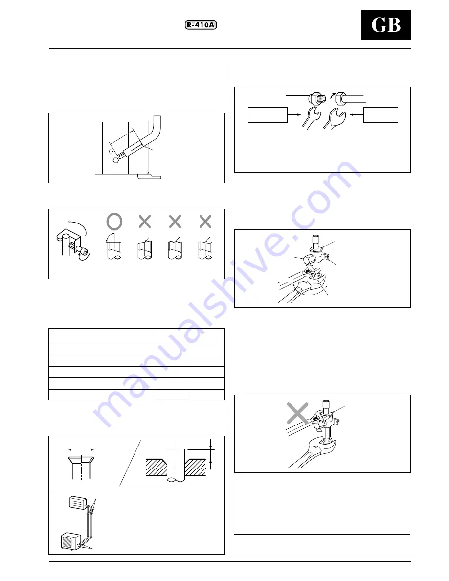
Pipe forming / positioning

• Pipe forming.

Form the pipe along with a marked line of the cabinet.

• End positioning of pipe.

Match the ends of both pipes at a distance of 85 mm apart from
the marked line.

Refrigerant piping

Flaring

1. Cut the pipe with a pipe cutter.

2. Insert a flare nut into the pipe, and flare the pipe.

As the flaring sizes of R410A differ from those of refrigerant R22,
the flare tools newly manufactured for R410A are recommended.

Table V: Pipe outer diameter

• In case of flaring for R410A with the conventional flare tool, pull it

out approx. 0.5 mm more than that of R22 to adjust to the
specified flare size.
The copper pipe gauge is useful for adjusting projection margin
size.

A

B

Outer dia. of copper pipe

+ 0 

 mm

-0,4

R410A

R22

6,35

9,1

9,0

9,52

13,2

13,0

12,7

16,6

16,2

15,9

19,7

19,4

90˚

 Obliquity

 Roughness

 Warp

 Flare at indoor unit side

 Flare at outdoor unit side

Marked line

85 mm

lign the centres of the connecting pipes and tighten the flare nut
as strong as possible with your fingers.
Then fix the nut with a spanner and tighten it with torque wrench as
shown in the figure.

• As shown in the figure, use two spanners to unscrew or tighten

the valve flare nut, at gas side.
If using a single spanner, the nut cannot be tightened with
necessary tightening torque.
On the contrary, use a single spanner to loosen or tighten the flare
nut of the valve at liquid side.

REQUIREMENT:
1. Do not put the spanner on the cap. The valve may be broken.

2. If applying excessive torque, the nut may be broken according to

some installation conditions.

• After the installation work, be sure to check gas leak of connecting

part of the pipes with nitrogen.

• Pressure of R410A is higher than that of R22 (Approx. 1.6 times).

Therefore, using a torque wrench, tighten the flare pipe
connecting sections which connect the indoor/outdoor units at the
specified tightening torque.
Incomplete connections may cause not only a gas leak, but also a
trouble of the refrigeration cycle.

IMPORTANT:
Do not apply refrigerating machine oil to the flared surface.

 Cover

 Half union or packed valve

 Flare nut


Internally threaded side

C

D

 Externally threaded side

Fix with spanner.
Tighten with torque wrench.

 Cover


 Piping valve


Flare nut

Tightened
Loosened


E

F

Summary of Contents for XPOWER 38VYX050

Page 1: ...38VYX050 38VYX080 L L O Y D S R E G I S TER QUALIT Y A S S U R A N C E IS O 900 1 INSTALLATION MANUAL...

Page 2: ...refrigerant cylinders are pink R 410A refrigerant cylinders have a dip tube which allows liquid to flow out with the cylinder in a vertical position with the valve at the top R 410A systems should be...

Page 3: ...other than the specified refrigerant into the refrigeration cycle If air or any other gas is mixed in the refrigerant the gas pressure in the refrigeration cycle becomes abnormally high and it may cau...

Page 4: ...add refrigerant at installation site 1 from 20 m to 30 m 38VYX 050 Add 20 g of refrigerant for every meter of pipe beyond 20 m 2 from 20 m to 50 m 38VYX 080 Add 40 g of refrigerant for every meter of...

Page 5: ...round the outdoor unit A place where the operation noise and discharged air are not given to your neighbors A place that is not exposed to a strong wind A place that does not block a passage When the...

Page 6: ...your fingers Then fix the nut with a spanner and tighten it with torque wrench as shown in the figure As shown in the figure use two spanners to unscrew or tighten the valve flare nut at gas side If u...

Page 7: ...e lower than the height of the outdoor unit The height of the obstacle should be lower than the height of the outdoor unit 150 or more 300 or more 300 or more 300 or more 200 or more 150 or more 500 o...

Page 8: ...or more Open the upper side and both right and left sides The height of obstacle at both front and rear side should be lower than the height of the outdoor unit Serial installation at front and rear...

Page 9: ...nd also seal the screws securely with silicone material etc so that water does not drop down Some conditions may cause dewing or dripping of water Drain nipple Table VI Optional Installation Parts loc...

Page 10: ...ed valve Gas side a little to check the air passes through 2 Tighten the flare nut again Execute vacuuming until the compound pressure gauge indicates 101kPa 76cmHg 1 Close handle Low completely Turn...

Page 11: ...g disconnect electrical connections before refrigerant connections IMPORTANT Make ground connection prior to any other electrical connections Power cable and connecting cable The installation fuse 25A...

Page 12: ...ashing Discharge temp error hot gas is too high Off EEPROM error On Communication error between IPDU No abnormal stop G Tr short circuit protection Detect circuit error Current sensor error Comp lock...

Page 13: ...other refrigerant from being charged each port diameter is changed In order to increase pressure resisting strength Charge hose x hose materials and port size are changed to 1 2 UNF 20 threads per in...

Page 14: ...050 080 Via R Sanzio 9 20058 Villasanta MI Italy Tel 039 3636 1 The manufacturer reserves the right to change any product specifications without notice November 2003 Supersedes July 2003 Printed in J...

Reviews: