


9
MOTOR
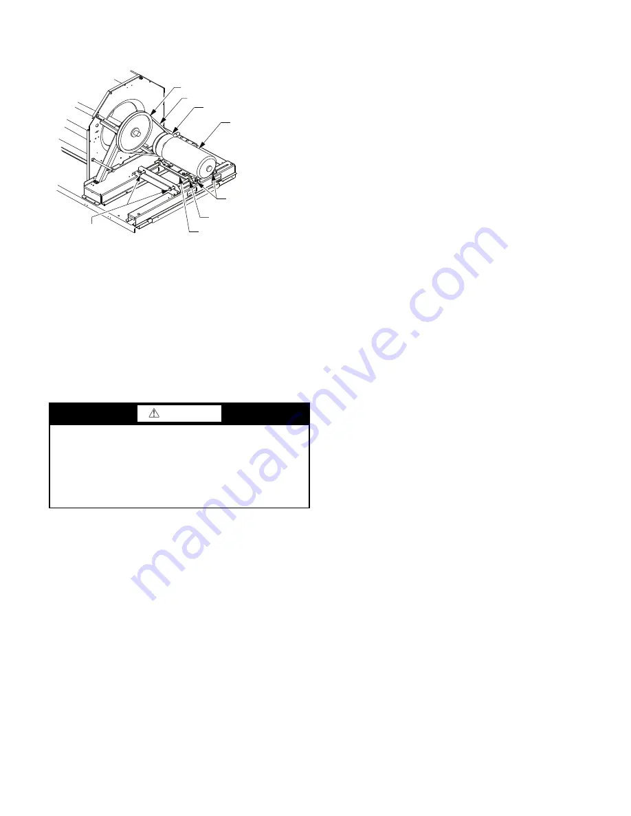
When replacing the motor, use the following steps. See Fig. 18.
Fig. 18 — Replacing Belt-Driven Motor
Replacing the Motor
Use the following steps to replace the belt-driven motor.
1. Turn off all electrical power to the unit. Use approved
lockout/tag-out procedures on all electrical power sources.
2. Remove cover on motor connection box.
3. Disconnect all electrical leads to the motor.
4. Loosen the two jack bolt jamnuts on the motor mounting
bracket.
5. Turn two jack bolts counterclockwise until motor assem-
bly moves closer to blower pulley.
6. Remove V-belt from blower pulley and motor pulley.
7. Loosen the four mounting bracket bolts and lock washers.
8. Remove four bolts, four flat washers, four lock washers
and four nuts attaching the motor mounting plate to the
unit. Discard all lock washers.
9. Remove motor and motor mounting bracket from unit.
10. Remove four bolts, flat washers, lock washers and single
external-tooth lock washer attaching motor to the motor
mounting plate. Discard all lock washers and external-
tooth lock washer.
11. Lift motor from motor mounting plate and set aside.
12. Slide motor mounting band from old motor.
13. Slide motor mounting band onto new motor and set motor
onto the motor mounting plate.
14. Remove variable pitch pulley from old motor and attach it
to the new motor.
15. Inspect variable pitch pulley for cracks and wear. Replace
the pulley if necessary.
16. Secure the pulley to the motor by tightening the pulley set-
screw to the motor shaft.
17. Insert four bolts and flat washers through mounting holes
on the motor into holes on the motor mounting plate.
18. On one bolt, place a new external-tooth lock washer
between the motor and motor mounting band.
19. Ensure the teeth of the external-tooth lock washer make
contact with the painted base of the motor. This washer is
essential for properly grounding motor.
20. Install four new lock washers and four nuts on the bolts on
the bottom of the motor mounting plate.
NOTE: Do not tighten the mounting bolts at this time.
21. Set new motor and motor mounting bracket back onto the
unit. See Fig. 18.
22. Install four bolts, four flat washers, four new lock washers
and four nuts attaching the motor assembly to the unit.
NOTE: Do not tighten the mounting bolts at this time.
23. Install motor drive V-belt to motor pulley and blower
wheel pulley. See CAUTION.
24. Align the motor pulley and blower wheel pulley using a
straight edge. See Fig. 13.
25. Adjust the V-belt tension using adjustment tool.
26. Turn two jack bolts clockwise, moving the motor assembly
away from the blower pulley, increasing the V-belt tension.
27. Tighten the four bolts securing the motor mounting brack-
ets to the unit. Torque four bolts to 120 ± 12 in.-lb (14 ±
1.4 Nm).
28. Remove cover on motor connection box.
29. Re-connect all electrical leads to the motor and replace the
connection box cover.
30. Re-connect all electrical power to the unit. Remove lock-
out tags on all electrical power sources.
31. Start unit and allow to run for a designated period.
32. Shut off unit and make any necessary adjustments to the V-
belt tension or the motor and blower wheel pulley alignment.
When replacing the motor, also replace the external-tooth lock
washer (star washer) under the motor mounting base; this is
part of the motor grounding system. Ensure the teeth on the
lock washer are in contact with the motor’s painted base.
Tighten motor mounting bolts to 120 ± 12 in.-lb.
Changing Fan Wheel Speed
Changing fan wheel speed by changing pulleys: The horse-
power rating of the belt is primarily dictated by the pitch diam-
eter of the smaller pulley in the drive system (typically the mo-
tor pulley in these units). Do not install a replacement motor
pulley with a smaller pitch diameter than provided on the orig-
inal factory pulley. Change fan wheel speed by changing the
fan pulley (larger pitch diameter to reduce wheel speed, small-
er pitch diameter to increase wheel speed) or select a new sys-
tem (both pulleys and matching belt).
Before changing pulleys to increase fan wheel speed, check the
fan performance at the target speed and airflow rate to deter-
mine new motor loading (bhp). Use the fan performance tables
(see Appendix C) or use the Packaged Rooftop Builder soft-
ware program. Confirm that the motor in this unit is capable of
operating at the new operating condition. Fan shaft loading in-
creases dramatically as wheel speed is increased.
To reduce vibration, replace the motor’s adjustable pitch pulley
with a fixed pitch pulley (after the final airflow balance adjust-
ment). This will reduce the amount of vibration generated by
the motor/belt-drive system.
See Tables 4 and 5 for VFD unit parameters.
CAUTION
EQUIPMENT DAMAGE HAZARD
Failure to follow this CAUTION can result in premature
wear and damage to equipment.
Do not use a screwdriver or a pry bar to place the new V-
belt in the pulley groove. This can cause stress on the V-belt
and the pulley resulting in premature wear on the V-belt
and damage to the pulley.
BLOWER PULLEY
V-BELT
MOTOR PULLEY
MOTOR
MOTOR MOUNTING
BRACKET BOLTS (4)
MOTOR MOUNTING
BRACKET (2)
JACK BOLT JAM NUT (2)
JACK BOLT (2)
Summary of Contents for WeatherMaster 50HC04
Page 32: ...32 Fig 63 RTU Open Overlay for Economizer Wiring ...
Page 33: ...33 Fig 64 VFD Overlay for W2770 Controller Wiring ...
Page 86: ...86 Fig C 50HC A07 PAC Control Diagram 208 230 3 60 460 575 3 60 APPENDIX D WIRING DIAGRAMS ...
Page 91: ...91 Fig H 50HC D12 PAC Control Diagram 208 230 3 60 460 575 3 60 APPENDIX D WIRING DIAGRAMS ...
Page 93: ...93 Fig J 50HC A04 A06 PAC Power Diagram 208 230 1 60 APPENDIX D WIRING DIAGRAMS ...
Page 95: ...95 Fig L 50HC A07 PAC Power Diagram 208 230 3 60 460 3 60 575 3 60 APPENDIX D WIRING DIAGRAMS ...
Page 100: ...100 Fig Q 50HC D11 PAC Power Diagram 208 230 3 60 APPENDIX D WIRING DIAGRAMS ...
Page 101: ...101 Fig R 50HC D11 PAC Power Diagram 460 3 60 575 3 60 APPENDIX D WIRING DIAGRAMS ...
Page 103: ...103 Fig T 50HC D14 PAC Power Diagram 208 230 3 60 APPENDIX D WIRING DIAGRAMS ...
Page 104: ...104 Fig U 50HC D14 PAC Power Diagram 460 3 60 575 3 60 APPENDIX D WIRING DIAGRAMS ...
Page 124: ...124 Fig AO PremierLink System A04 A06 Wiring Diagram APPENDIX D WIRING DIAGRAMS ...
Page 125: ...125 Fig AP RTU Open System Control A04 A06 Wiring Diagram APPENDIX D WIRING DIAGRAMS ...
Page 126: ...126 Fig AQ PremierLink System A07 D14 Wiring Diagram APPENDIX D WIRING DIAGRAMS ...
Page 127: ...127 Fig AR RTU Open A07 D14 Wiring Diagram APPENDIX D WIRING DIAGRAMS ...