


7
Adjust belt tension by loosening the motor mounting plate
front and rear bolts and sliding the plate toward the fan (to re-
duce tension) or away from fan (to increase tension). Ensure
the blower shaft and the motor shaft are parallel to each other
(pulleys aligned). When finished, tighten all bolts and torque to
65 to 70 in.-lb (7.4 to 7.9 Nm).
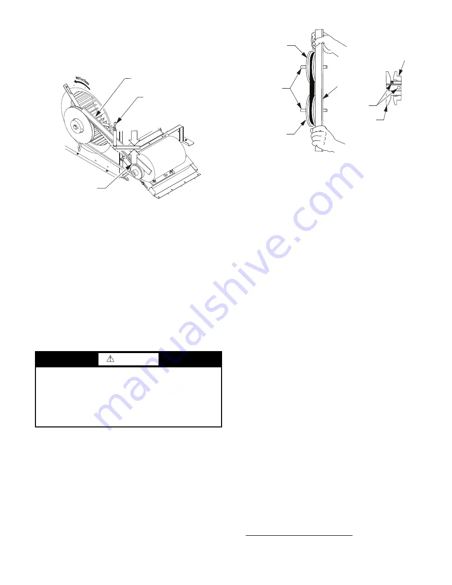
Fig. 12 — Checking Blower Motor Belt Tension
Replacing the Belt
NOTE: Use a belt with same section type or similar size. Do not
substitute a FHP-type belt. When installing the new belt, do not
use a tool (screwdriver or pry-bar) to force the belt over the pulley
flanges; this will stress the belt and cause a reduction in belt life.
Damage to the pulley can also occur.
Use the following steps to replace the V-belt. See Fig. 11.
1. Loosen the front and rear motor mounting plate bolts.
2. Push the motor and its mounting plate towards the blower
housing as close as possible to reduce the center distance
between fan shaft and motor shaft.
3. Remove the belt by gently lifting the old belt over one of
the pulleys.
4. Install the new belt by gently sliding the belt over both
pulleys and then sliding the motor and plate away from the
fan housing until proper tension is achieved.
5. Check the alignment of the pulleys and adjust if necessary.
6. Tighten all bolts and torque to 65 to 70 in.-lb (7.4 to
7.9 Nm).
7. Check the tension after a few hours of runtime and re-
adjust as required.
ADJUSTABLE-PITCH PULLEY ON MOTOR
The motor pulley is an adjustable-pitch type that allows a ser-
vicer to implement changes in the fan wheel speed to match as-
installed ductwork systems. The pulley consists of a fixed
flange side that faces the motor (secured to the motor shaft)
and a movable flange side that can be rotated around the fixed
flange side that increases or reduces the pitch diameter of this
driver pulley. (See Fig. 13.)
Fig. 13 — Supply-Fan Pulley Adjustment
As the pitch diameter is changed by adjusting the position of
the movable flange, the centerline on this pulley shifts laterally
(along the motor shaft). This creates a requirement for a re-
alignment of the pulleys after any adjustment of the movable
flange. Reset the belt tension after each realignment.
Inspect the condition of the motor pulley for signs of wear.
Glazing of the belt contact surfaces and erosion on these sur-
faces are signs of improper belt tension and/or belt slippage.
Replace pulley if wear is excessive.
Changing the fan speed:
1. Shut off unit power supply. Use proper lockout/tag-out
procedures.
2. Loosen belt by loosening fan motor mounting nuts. (See
Fig. 11.)
3. Loosen movable pulley flange setscrew. (See Fig. 13.)
4. Screw movable flange toward fixed flange to increase
speed and away from fixed flange to decrease speed.
Increasing fan speed increases load on motor. Do not
exceed the maximum specified speed.
5. Set movable flange at nearest keyway of pulley hub.
Tighten setscrew and torque to 65 to 70 in.-lb (7.4 to
7.9 Nm).
ALIGNING BLOWER AND MOTOR PULLEYS:
1. Loosen blower pulley setscrews.
2. Slide blower pulley along blower shaft. Make angular
alignment by loosening motor mounting plate front and
rear bolts.
3. Tighten blower pulley setscrews and motor mounting
bolts. Torque bolts to 65 to 70 in.-lb (7.4 to 7.9 Nm).
4. Recheck belt tension.
Bearings
The fan system uses bearings featuring concentric split locking
collars. A Torx
1
T-25 socket head cap screw is used to tighten
the locking collars. Tighten the locking collar by holding it
tightly against the inner race of the bearing. Tighten the socket
head cap screw. Torque cap screw to 65 to 70 in.-lb (7.4 to
7.9 Nm). See Fig. 14. Check the condition of the motor pulley
for signs of wear. Glazing of the belt contact surfaces and ero-
sion on these surfaces are signs of improper belt tension and/or
belt slippage. Pulley replacement can be necessary.
CAUTION
EQUIPMENT DAMAGE HAZARD
Failure to follow this CAUTION can result in premature
wear and damage to equipment.
Do not use a screwdriver or a pry bar to place the new V-
belt in the pulley groove. This can cause stress on the V-belt
and the pulley resulting in premature wear on the V-belt
and damage to the pulley.
BROWNING BELT
TENSION CHECKER
STRAIGHTEDGE
1/2”
(1.3 cm)
BELT
DEFLECTION
1. Torx is a registered trademark of Acument Intellectual Properties,
LLC.
STRAIGHT EDGE
MUST BE PARALLEL
WITH BELT
SETSCREWS
MOTOR AND
FANSHAFTS
MUST BE
PARALLEL
FIXED FLANGE
MOVABLE
FLANGE
SINGLE - GROOVE
FAN PULLEY
MOTOR PULLEY
Summary of Contents for WeatherMaster 50HC04
Page 32: ...32 Fig 63 RTU Open Overlay for Economizer Wiring ...
Page 33: ...33 Fig 64 VFD Overlay for W2770 Controller Wiring ...
Page 86: ...86 Fig C 50HC A07 PAC Control Diagram 208 230 3 60 460 575 3 60 APPENDIX D WIRING DIAGRAMS ...
Page 91: ...91 Fig H 50HC D12 PAC Control Diagram 208 230 3 60 460 575 3 60 APPENDIX D WIRING DIAGRAMS ...
Page 93: ...93 Fig J 50HC A04 A06 PAC Power Diagram 208 230 1 60 APPENDIX D WIRING DIAGRAMS ...
Page 95: ...95 Fig L 50HC A07 PAC Power Diagram 208 230 3 60 460 3 60 575 3 60 APPENDIX D WIRING DIAGRAMS ...
Page 100: ...100 Fig Q 50HC D11 PAC Power Diagram 208 230 3 60 APPENDIX D WIRING DIAGRAMS ...
Page 101: ...101 Fig R 50HC D11 PAC Power Diagram 460 3 60 575 3 60 APPENDIX D WIRING DIAGRAMS ...
Page 103: ...103 Fig T 50HC D14 PAC Power Diagram 208 230 3 60 APPENDIX D WIRING DIAGRAMS ...
Page 104: ...104 Fig U 50HC D14 PAC Power Diagram 460 3 60 575 3 60 APPENDIX D WIRING DIAGRAMS ...
Page 124: ...124 Fig AO PremierLink System A04 A06 Wiring Diagram APPENDIX D WIRING DIAGRAMS ...
Page 125: ...125 Fig AP RTU Open System Control A04 A06 Wiring Diagram APPENDIX D WIRING DIAGRAMS ...
Page 126: ...126 Fig AQ PremierLink System A07 D14 Wiring Diagram APPENDIX D WIRING DIAGRAMS ...
Page 127: ...127 Fig AR RTU Open A07 D14 Wiring Diagram APPENDIX D WIRING DIAGRAMS ...