36
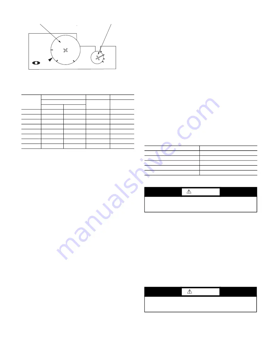
Fig. 24 — Motor Starter Setting
Table 21 — Evaporator and Condenser
Motor Starter Settings
MAINTENANCE
Cleaning
The unit should be thoroughly cleaned inside and out. Frequency
of cleaning will depend on unit location and area conditions.
Drains must be kept free of dirt and trash. Coils can be cleaned
with a stiff brush or vacuum cleaner. Coil can be reached through
access panels.
Inspection
Check coil baffles for tight fit to prevent air from bypassing the
coil. Check panels for air leakage, particularly those sealing the
fan and coil compartments. Check for loose electrical connections,
proper refrigerant charge, and refrigerant piping leaks.
Air Filters
Air filters may be installed on the condenser air inlet. Air filters
should be replaced or cleaned on a regular basis depending on
how dirty the operating environment is. Failure to clean air filters
regularly will result in loss of unit performance and possible nui
-
sance tripping of the high-pressure switch.
Condensate Drain
The drain pan and trap should be cleaned at least twice per year.
After cleaning, test the condensate drain for proper operation by
pouring a bucket of water into the condensate drain pan. The water
should flow out immediately and evenly.
Checking System Charge
NOTE: Condenser and evaporator airflow must be properly set
before checking system charge.
The 50XCA units are shipped with full operating charge. If re
-
charging is necessary:
1. Insert thermometer bulb in insulating rubber sleeve on liquid
line near filter drier. Use a digital thermometer for all tem
-
perature measurements. DO NOT use a mercury or dial-type
thermometer.
2. Connect refrigerant pressure gage to discharge line near com
-
pressor.
3. After unit condition have stabilized, read head pressure on
discharge line gage.
4. NOTE: Operate unit a minimum of 15 minutes before check
-
ing charge.
5. From standard Pressure-Temperature chart for R-410A, find
equivalent saturated condensing temperature.
6. Read liquid line temperature on thermometer; then subtract
from saturated condensing temperature. The difference
equals subcooling temperature.
7. Compare the subcooling temperature with the normal tem
-
perature listed in Table 22. If the measured liquid line tem
-
perature does not agree with the required liquid line
temperature, ADD refrigerant to raise the temperature or
REMOVE refrigerant (using standard practices) to lower the
temperature (allow a tolerance of ± 3°F).
Example:
Head pressure (from gage)416.4 psig
Saturated condensing temp (from chart)120°F
Liquid line temp (from thermometer)100°F
Subcooling (by subtraction)20°F
Table 22 — Subcooling Temperature
*Saturated condensing temperature at compressor minus liquid line tem-
perature.
NOTE: Do not vent or depressurize unit refrigerant to atmosphere.
Remove and recover refrigerant following accepted practices.
Access Panel Removal
TOP PANEL
Remove 3 to 6 screws, pull out panel, and remove.
CONTROL PANEL
Remove 4 screws and remove the panel.
BOTTOM PANEL
Remove 3 to 6 screws in bottom panel and lift up to remove the
panel.
Evaporator-Fan Motor Removal
NOTE: Motor power wires need to be disconnected from control
box terminals before motor is removed from unit.
HP
208-230 V
460 V
575 V
FLA
FLA
FLA
208V
230V
0.50
1.8
2.2
1.1
0.9
0.75
2.5
2.6
1.3
1.0
1.00
3.4
3.0
1.5
1.1
1.50
4.6
4.2
2.1
1.6
2.00
6.0
5.6
2.8
2.1
3.00
9.2
8.6
4.3
3.4
5.00
14.5
13.6
6.8
5.4
7.50
21.5
19.4
9.7
7.5
1.9
1.6
1.3
M
M-O
A-O
A
RESE
T-
O
CLASS 20
TEST
OVERLOAD SETPOINT WHEEL
MOTOR OVERLOAD RESET WHEEL
UNIT 50XCA
SUBCOOLING*
06
20°
08
17°
12-14
21°
16
18°
24
25°
WARNING
To prevent personal injury, wear safety glasses and gloves
when handling refrigerant. Do not overcharge system — this
can cause compressor flooding.
CAUTION
Before attempting to remove fan motors or motor mounts,
place a piece of plywood over evaporator coils to prevent coil
damage.


