


24VNA6 / 25VNA4: Service Manual
Manufacturer reserves the right to change, at any time, specifications and designs without notice and without obligations.
39
Vapor Injection Electronic Exp. Valve (EXV VI)
(5 Ton Models)
The EXV-VI is an electronically controlled needle valve for regulating
refrigerant flow during heating operation. The EXV-VI is driven by a
12VDC, 2-phase, uni-polar stepper motor. The EXV-VI has a 475 step
range between fully closed and fully open. The PCM drives the EXV at a
rate of 77 steps per second. The PCM initializes the EXV-VI to the
closed position when power is applied to the equipment. This process
takes approximately 7 seconds.
When operating at full capacity in a cooling at high ambient
temperatures or in heating at low ambient temperatures in efficiency
mode, the EXV-VI is actively controlled to maintain discharge super
heat to a control target value. When operating at a lower capacity, in
comfort mode, at mild ambient temperatures, or not running, the
EXV-VI is closed.
The brazed plate heat exchanger assembly is mounted to the base pan
using a grommet and stud similar to the accumulator mounting. The
BPHE assembly also contains a muffler either between the BPHE and
the compressor or between the BPHE and the liquid service valve.
Additionally, there are rubber dampers attached to the tube between the
BPHE and the compressor.
If any part of the BPHE needs to be repaired then only a
factory-authorized part shall be used to replace the entire vapor injection
assembly. It is recommended that the coil be removed to replace the
BPHE assembly. Upon replacement the grommet and clip used for
mounting can be re-used and the dampers shall be re-attached to the
BPHE assembly using a wire tie. Failure to re-attach the dampers could
result in a premature tube failure."
REFRIGERATION SYSTEM REPAIR
Leak Detection
New installations should be checked for leaks prior to complete
charging. If a system has lost all or most of its charge, system must be
pressurized again to approximately 150 psi minimum and 375 psi
maximum. This can be done by adding refrigerant using normal charging
procedures or by pressurizing system with nitrogen (less expensive than
refrigerant). Nitrogen also leaks faster than refrigerants. Nitrogen
cannot, however, be detected by an electronic leak detector. (See
.)
A95422
Fig. 40 – Electronic Leak Detection
Assuming that a system is pressurized with either all refrigerant or a
mixture of nitrogen and refrigerant, leaks in the system can be found
with an electronic leak detector that is capable of detecting specific
refrigerants.
If system has been operating for some time, first check for a leak
visually. Since refrigerant carries a small quantity of oil, traces of oil at
any joint or connection is an indication that refrigerant is leaking at that
point.
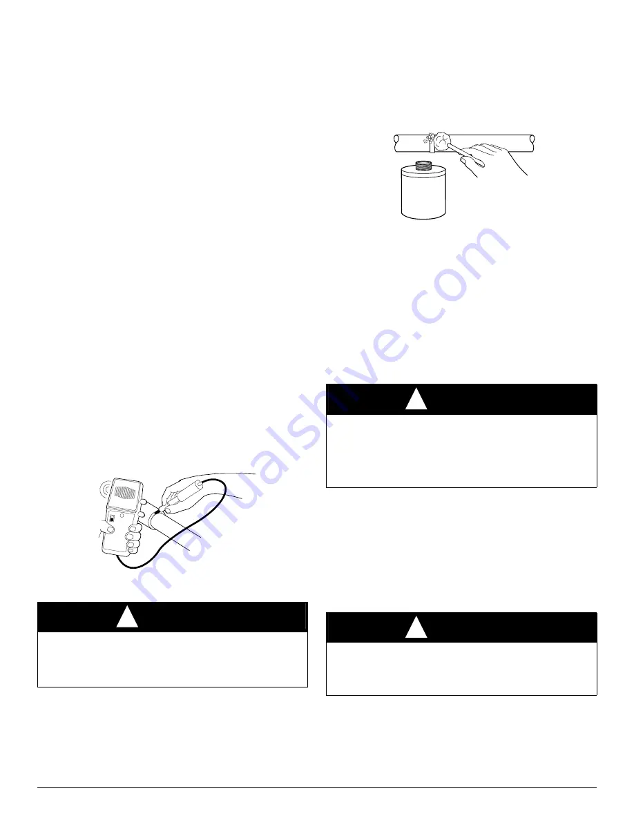
A simple and inexpensive method of testing for leaks is to use soap
bubbles. (See
.) Any solution of water and soap may be used.
Soap solution is applied to all joints and connections in system. A small
pinhole leak is located by tracing bubbles in soap solution around leak. If
the leak is very small, several minutes may pass before a bubble will
form. Popular commercial leak detection solutions give better,
longer-lasting bubbles and more accurate results than plain soapy water.
The bubble solution must be removed from the tubing and fittings after
checking for leaks as some solutions may corrode the metal.
A95423
Fig. 41 – Bubble Leak Detection
You may use an electronic leak detector designed for specific refrigerant
to check for leaks (See
). This unquestionably is the most efficient
and easiest method for checking leaks. There are various types of
electronic leak detectors. Check with manufacturer of equipment for
suitability. Generally speaking, they are portable, lightweight, and
consist of a box with several switches and a probe or sniffer. Detector is
turned on and probe is passed around all fittings and connections in
system. Leak is detected by either the movement of a pointer on detector
dial, a buzzing sound, or a light.
In all instances when a leak is found, system charge must be recovered
and leak repaired before final charging and operation. After leak testing
or leak is repaired, replace liquid line filter drier, evacuate system, and
recharge with correct refrigerant quantity.
Coil Removal
Coils are easy to remove if required for compressor removal, or to
replace coil.
1. Shut off all power to unit.
2. Recover refrigerant from system through service valves.
3. Break vacuum with nitrogen.
4. Remove top cover.
5. Remove screws in base pan to coil grille.
6. Remove coil grille from unit.
7. Remove screws on corner post holding coil tube sheet.
8. Use midget tubing cutter to cut liquid and vapor lines at both sides
of coil. Cut in convenient location for easy reassembly with copper
slip couplings.
9. Lift coil vertically from basepan and carefully place aside.
10. Reverse procedure to reinstall coil.
11. Replace filter drier, evacuate system, recharge, and check for
normal systems operation.
WARNING
!
PERSONAL INJURY AND UNIT DAMAGE HAZARD
Failure to follow this warning could result in personal injury or death.
Due to the high pressure of nitrogen, it should never be used without a
pressure regulator on the tank.
BEEP
BEEP
WARNING
!
ELECTRICAL SHOCK HAZARD
Failure to follow this warning could result in personal injury or death.
Before installing, modifying, or servicing system, main electrical
disconnect switch must be in the OFF position. There may be more than
1 disconnect switch. Lock out and tag switch with a suitable warning
label.
WARNING
!
FIRE HAZARD
Failure to follow this warning could result in personal injury or
equipment damage.
Cut tubing to reduce possibility of personal injury and fire.
LEAK
DETECTOR
SOLUTION


